| |
![]()
 |
| |
|
Intrepid-Class Light Explorer
UNITED FEDERATION OF PLANETS: STARFLEET DIVISION Advanced Technical Specifications for the Intrepid-Class Production Vehicle
1.0
INTREPID-CLASS INTRODUCTION
Pursuant to Starfleet Exploration Directives 1015.9 & 1020.16, Starfleet Defense Directives 200.0, 197.5 & 197.6, and Federation Security Council General Policy, the following objectives have been established for an Intrepid Class Starship: 1. Provide
autonomous capability for full execution of Federation defensive,
cultural,
scientific, and explorative policy in deep space or border territory.
Length:
342.5 meters Hull:
Duranium-Tritanium
composite
Editor's Note: History written by Kurt Goring - based on information found in Star Trek: First Contact, Star Trek: Voyager, Star Trek Technical Manual, Star Trek: The Next Generation Technical Manual, Star Trek: Deep Space 9 Technical Manual, and Star Trek: The Magazine. The style of the history is based on histories presented in the Star Trek Spaceflight Chronology by Stan Goldstein, Fred Goldstein, and Rick Sternbach. Please keep in mind that this is a history developed based on canon information presented in various sources and filled in with logical conjecture. From stem to stern, the Intrepid class is one of the most advanced starships in Starfleet. The class employs a new warp core, variable geometry warp nacelles, and was the first to field both bio-neural gelpaks and the Emergency Medical Hologram system. Nearly three-hundred-fifty meters long, the Intrepid class is built sleek and long, sporting the fastest top speed on record for a Starfleet vessel with the exception of the new Sovereign class and the ground-breaking Prometheus class in field trials currently. The tilting, wing-like nacelles can shift microns in their positions, emitting minutely adjustable warp fields that are more efficient and safer when traveling in subspace. This, combined with new verterion manufacturing and the APD-01 Warp Core, makes it’s propulsion systems super-advanced. The class serves multiple functions based on its load out, as well as size. An Intrepid could be seen on patrol or escort duty as easily as long-range exploration or survey. State of the art computers give it unprecedented storage capacity, access speed, and rigor conditioning. This, combined with a wide array of sensors covering a large amount of the exposed surface, makes the Intrepid class a premier ship of the line for Starfleet’s scientific endeavors. Fast, agile, and well armed, these science ships are among the more capable multi-role platforms when faced with combat situations. Advanced shielding and Type-X phaser arrays equip it admirably, with several representatives of the class serving during the Dominion War with amazing success. Perhaps the most visible example of the superior nature of the Intrepid class is one of its first members. Third of it’s class, the USS Voyager made it across the Delta Quadrant aided by it’s own technology to a huge degree. The data returned by its crew has placed it permanently in the pantheon of most effective ship classes in Starfleet history.
By most accounts, the Intrepid class Project was begun July 4th 2361, the day Starfleet Admiral Nobuo Imagawa, speaking at a gathering of Utopia Planitia Yard technical staff, called for the creation of a new family of fast interstellar vessels. By this date, the Galaxy class was in the final stages of development, but even as Starfleet pressed for large, multi-mission vessels, the need for smaller vessels was becoming apparent. While the USS Galaxy NX-70637, USS Yamato NCC-71807, and USS Enterprise NCC-1701-D underwent final systems installations and testing, Admiral Imagawa spoke of the need for many different types of starships, shuttles, and support facilities to meet the growing need of crisis points in the galaxy. Among the ship types outlines in the preliminary Starfleet requirement briefs was a fast, powerful, ‘troubleshooter’ initially listed as Planform SV-65. This ship concept, created in basic form by the combined structures groups of McKinley Spacedock and Utopia Planitia Yards, would need to maintain a low-cruise factor of 7.75 for 16 days, a high-cruise warp of 9.2 for 2.25 days, and a dash-cruise speed of Warp 9.975 for 12.65 hours. It would support a crew of 223, would have swappable interior pressurized modules, and would mount defensive weaponry at least equal to the Galaxy-class phasers and photon torpedoes. A wide variety of primary mission types for the new ship – from threat-force point interception and large battle group support to covert intelligence gathering – was pared down to space defensive combat to protect Starfleet and Federation assets, and a continued scientific exploration during patrol intervals (C. Forrester, ASDB Journal, 05Nov2361) Starship
Geometry: Materials processing, fabrication techniques, and vessel maintenance cycles were evolved directly from those applied to the Excelsior, Ambassador and Galaxy classes. By Stardate 38956.00, eight computer warp stress and volumetric studies yielded the first review configuration, SV-65H. This vessel featured a 61” elliptical saucer section integrated with engineering hull, fixed pylons and nacelles, and a large ejectable bridge module to augment the standard lifeboats. No saucer separation capability was required. On January 1st 2362, the SV-65 program was officially titled the Intrepid class Project. Continued studies of warp fields and their interaction with the space and subspace environments led to six further planform modifications, with data on hull volumetrics, internal volume usage, and simulated warp and impulse performance being analyzed by the Advanced Starship Design Bureau (ASDB) for optimal mission efficiency. By the end of 2363, additional performance data from the USS Enterprise and USS Yamato shakedown flights had been incorporated into the Intrepid warp propulsion simulations. Warp
Systems: The design of reactor had originally been applied to the Constitution-class starships such as the USS Enterprise NCC-1701, and the return to the swirl chamber allowed Starfleet engineers an opportunity to increase structural integrity and power output. The reactor’s magnetic constrictors, matter and antimatter injectors, and plasma transfer conduits (PTCs) were designed to be assembled by computer-controlled formers and gamma welders. Advances in warp plasma containment and transport allowed for a hinged pylon. This modification was intended to give the ship a better warp factor-to-reactant usage ratio. It later emerged that it had the fortunate by-product of eliminating the kind of spatial damage caused by earlier designs of warp engine that had been uncovered by Dr. Rabal and Serova (Rabal, Journal of Warp Dynamics Vol. 1137). The complete warp core was designed from the outset to be ejectable in case of an emergency. Components for a second core were stored within the engineering hull, though assembly and flight testing by a crew in deep space could take up to a week. Second
Review: Other changes from first review hull included smaller warp coil sets, larger shuttlebay capacity, crew reduction to 168, smaller Deck 1 module, and increased internal space for laboratories, storage, and consumables. The forward auxiliary deflector remained in the second review hull, through warp and impulse performance tests suggested that a thinner, edge-mounted unit might reduce the Particles and Field Drag Index (PFDI) from 0.0033 to 0.0014. The larger figure was within tolerances and the deflector was integrated into the hull with minor rerouting of EPS and ODN conduits and associated controller hardware. Design
Freeze: Computer, human, and cetacean analysis recommended changes to the primary hull on the forward edge, Deck 2 surface contours, and aft attachment blends to the engineering hull, all as a result of warp efficiency simulations. Structures and systems that were not fully integrated by the third review were accepted as yard changes, and upgrades would be applied to each ship as it was constructed. Final systems improvements designed and approved for installation by April 2368 included phasers, lifeboats, RCS thruster quads, gravity generators, Multi-directional Sensor Array (MSA), and the AeroShuttle. Vessel frame IC-103, USS Voyager NCC-74656, was the first ship to receive all hardware as original installations, after testbed results were gathered from its older Spacedock siblings (P. Bryce, Starfleet Construction Proceedings, Data Index RI-456/32/456). Armaments: Five phaser emitters –two dorsal, to ventral, one ventral lower – and two forward photon torpedo launchers grew to 13 phaser emitters –adding two dorsal aft, two ventral aft, two pylon, two dorsal fantail – and four photon torpedo launchers. The additional aft-firing tubes and increased phaser coverage insured that the Intrepid class could counter most known and predicted threat vessels of similar size and mass, in battle group, escorted, or solitary operation scenarios. Lifeboats were enlarged slightly to accommodate six crew, up from the original four. The relatively small volume lost within the starship could also be used to give each lifeboat an operating lifetime of almost 16 months, and a total impulse range of 0.25 light-years. Jettisonable hatches were replaced by hinged covers in the event that shipboard emergencies were averted following pod launch. Improved communications and life-support systems could be shared through the docking of multiple lifeboats in ‘gaggle mode’, first proven with the Galaxy class. EPS
System
Upgrades: These same conduits and valves were designed into the new gravity plating, a carpet of thousands of miniaturized graviton generators, each measuring 3.23 cm across. The hexagonal valves responded to plasma pressure variations, averaging out power distribution, and allowing for up to 10 percent generator failure without a perceptible change in local gravity. In earlier starships, larger and fewer graviton devices had occasionally produced unpleasant balance and minor nausea effect, particularly in rookie crewmembers. Sensor
Systems: The AeroShuttle was the only upgraded component to the Intrepid class that remained in the development cycle long after the other major systems had been frozen and released for fabrication and assembly. Based on the existing Starfleet runabout platform, the AeroShuttle was given a 450 percent increase in atmospheric flight and hover endurance over standard shuttlecraft. This was accomplished through the use of hybrid microfusion and EM driven airflow coil engines. Although the AeroShuttle spaceframe and basic systems were completed on Stardate 46875.3, final outfitting of mission-specific hardware was delayed until simulations and flight testing with the USS Intrepid could be completed. All seven Intrepid class in the initial procurement were constructed at the Utopia Planitia Yards in Mars orbit, minus their active and backup warp cores, and also lacking their final outer surface plating and distinctive coloration. Each vessel crossed the distance from Mars to Earth Station McKinley under low impulse, recording systems performance data on the way. Commissioning
Date: A 15-day series of impulse tests, which verified the integrity of the vessel and systems operation at sublight velocities, culminated in Voyager accelerating to Warp 1.03 with the USS Hauck flying formation for engineering support and emergency backup. Three weeks of warp flight tests added to the Intrepid class knowledge base and insured that Voyager’s computer cores and bio-neural gel packs could receive operational programming loads for deployment in the Alpha Quadrant. USS Voyager, under the command of Captain Kathryn Janeway, received her first patrol assignment on Stardate 48183.5. All in-flight systems data continued to be transmitted to Starfleet Command for evaluation along a range of velocities from inertial stop to Warp 9.986 and for distances up to 45 light-years, with subspace comm relays handling the encrypted telemetry loop. Subsequent operations validated the effectiveness of the class design and upgrades from previous Starfleet vessels. Voyager would provide only a few months of usable data before its disappearance in the Delta Quadrant. However, the stored information and lessons learned by its crew proved invaluable upon her return, a testament to the designers and engineers who stood upon the shoulders of giants to build her.
Layout: Ovoid layout typical of most Federation starships, the Intrepid class Bridge sports some of the most advanced technology and command-capabilities. Rearmost, the Intrepid Bridge is served by a large bank of consoles and data-readout screens. Center of that area is the Master Systems Display. From the MSD, all of the crew can get a compressed view of the ship and major systems for on-the-fly analysis. Control consoles flank the MSD on either side, running everything from incoming sensor data, to communications and auxiliary systems control. Starboard of the information center, just past the starboard side turbolift, is the Chief Tactical Officer’s console. Behind the forward-facing console is a larger area, with bigger displays and additional control infrastructure. This area is maintained mostly for internal security and manned by the Chief Tactical Officer’s assistant or similar. In typical configuration, the Chief Tactical Officer is in primary control of external security and weapons systems with the sister console configured for more sensor work and management of internal security. Tactical console usage is extremely limited; only Beta-2 Tactical clearance personnel can use it, and the user must input special codes to even get access to the massive amounts of computer links that give tactical nearly limitless information at the ship's disposal. For full access, the console's security subsystem can run a battery of scans on the user, including thermal, biological, retinal, and vocal tests. If all of these are passed, full access to the ship's offensive and defensive systems is made available. Across from the tactical kiosk is the Operations Manager’s post. From there, he or she has access to and/or control over ship’s internal systems, power flow, sensor data, communications, and transporter control. As one of the most important positions at any one time, the Operations kiosk is always manned. The two turbolifts on the bridge can handle normal transit around the ship. Also, an emergency ladder connects the bridge to Deck Three. Forward of the upper ship operations areas are doorways on port and starboard sides of the bridge. To port, access to the briefing room is provided. Inside is a large table for seating a minimum of eight officers, as well as displays, and a large set of viewports for vista. Starboard access leads to the Captain’s Ready Room. As the captain’s personal office, many command decisions are made there instead of the bridge. Directly forward of the command area and sunken down by two steps is the Conn. From this position, the Flight Control Officer serves as helmsman and navigator for the Intrepid class. The Conn has access to a wide array of ship systems, including Engineering data as the Chief of Helm often serves as a bridge liaison to Engineering. To the right of the Conn sits the Chief Engineer. Though far better served in Main Engineering, the Engineer is often needed on the bridge to provide analysis and control ‘on site’, as it were. This location is manned by a single officer, with wraparound consoles and access to almost all ship controls. . Typical configuration keeps a scaled down version of the master systems display keyed to display problems visually, as well as dedicated screens showing the status of the warp drive and structural integrity systems. Directly opposite sits the Chief Science Officer in a similar console. It has access to all science, navigational, sensor, and communications systems. It can be configured to operate in tandem with other consoles, although security links and all other non-science data are restricted to the main console. Center of the bridge is the command chairs – one each for the Captain and First Officer. The first officer’s chair is on the left, when facing forward, and includes screens for reviewing ship status reports on the fly. On the right, is the Captain’s chair. Both face the viewscreen directly behind the unified Helm. Two pods are reserved for the top four officers in the chain of command on the vessel because they are the last four to leave the ship. These are located on behind the main bridge through an access way. As the number of experienced Captains dwindles in Starfleet, the notion of a Captain going down with his ship has been abolished. If the ship is abandoned, the top four officers in the chain of command will wait until everyone else is off the ship, opt to arm the auto-Destruct (not always necessary, but there if needed), and then leave in the two escape pods. Each pod can support two people for 72 hours in space, and has a maximum speed of half impulse.
Located on Deck 11, Main Engineering is the ‘heart’ of the ship, comparable to the bridge as ‘brain’. It has access to almost all systems aboard the starship, and manages repairs, power flow, and general maintenance. Entrance to Main Engineering is provided by two large blast doors that can be closed incase of internal or external security issues. Just inside of that is an observation area where technicians monitor various systems of the ship. Farther in from observation area is the warp core and main control systems –the path to which is provided by removable floor paneling hiding additional systems but providing easy and fast access to them. A red guardrail circles the APD-01 Warp Core from Mercurion Inova. Faint blue lights display the reaction along the entire length of the core – an advancement that surpasses that of its contemporaries and paved the way to safer, more fuel efficient, and environmentally responsible engines. Off to the port side of Main Engineering is the Chief Engineer’s Office, which is equipped with a diagnostics table, assembly and repair equipment, a small replicator, and a personal use console with built-in private viewscreen. On Starboard, there is an open work area for projects, long-term assignments, and situational analysis. A second tier rings the second level of Main Engineering. A small single-person elevator, as well as a ladder on the opposite end, provides access to this catwalk. Access
to the
Jefferies
Tubes is provided in various places on both the First and Second Tier
of Main
Engineering.
This multi-room department is located in a restricted area on Deck 14. Within it are the entrances to the phaser range, the auxiliary weapon control room and to the Ship's Armory, as well as the office of the Chief of Security. Security Office: The Chief of Security’s office is decorated to the officer's preference. It contains a work area, a personal viewscreen, a computer display, and a replicator. Brig: Located on Deck 15, the brig is a restricted access area whose only entrance is from within the Security Department on Deck 14. The Intrepid class vessel has four double occupancy cells, which contain beds, a retractable table and chairs, a water dispenser, and sanitary facilities. The cells are secured with a level-10 forcefield emitter built into each doorway. Note: The Intrepid class Starship carries modular units for constructing additional brig facilities in the cargo bays. Internal Forcefields: Controlled from the bridge or from the Security office on Deck 14, forcefields can be activated throughout the ship, effectively sealing off sections of the hallway from the remainder of the vessel. Internal Sensors: Used to monitor the internal security of the ship. They can identify the location of specific crewmembers that are wearing their commbadge. They can be used to determine the general location of any person on board the ship, based on the entry of specific variables by the Tactical officer. Ship's Armory: This room is located in a restricted area on Deck 14 and is under constant guard. The room is sealed with a level 10 forcefield and can only be accessed by personnel with Level-4 or above security clearance granted by the Command staff or Chief of Security. Inside the armory is a work area for maintenance and repair of phasers as well as multiple sealed weapons lockers. The Intrepid class starship carries enough type-I and type-II phasers to arm the entire crew. Type-III phaser rifle and the new compression phaser rifles are available as well, but only in enough numbers to arm approximately 1/3 of the crew. Heavy ordnance is available in limited numbers. Armory
Inventory
includes:
Phaser Array Arrangement: The dorsal saucer section is covered by four phaser strips; two of which extend from the aft curvature, along the length of the saucer and stop short of the auxiliary deflector incision. The aft firing arc is covered by two smaller arrays angled on the rear of the saucer section. The relative bottom of the ship is protected by two similar arrays as on the dorsal saucer section, extending to the rear of the saucer and following the curve to the aux deflector incision. Along with those arrays, are two small aft-angled phaser strips similar to the dorsal aft-fire strips. Additional protection is provided by a single array that extends laterally across the ventral engineering hull just fore of the warpcore ejection port. Far-aft strips are provided on the underside of the mobile nacelle pylons and under the shuttlebay landing deck on the underside of the ship for a total ship’s complement of 13 arrays. Phaser Array Type: The Intrepid class utilizes the Type X array system. The thirteen arrays are all Type-X, the new standard emitter. Each array fires a steady beam of phaser energy, and the forced-focus emitters discharge the phasers at speeds approaching .986c (which works out to about 182,520 miles per second - nearly warp one). The phaser array automatically rotates phaser frequency and attempts to lock onto the frequency and phase of a threat vehicle's shields for shield penetration. Phaser Array Output: Each phaser array takes its energy directly from the impulse drive and auxiliary fusion generators. Individually, each type X -emitter can only discharge approximately 5.1 MW (megawatts). However, several emitters (usually two) fire at once in the array during standard firing procedures, resulting in a discharge approximately 10.2 MW. Phaser Array Range: Maximum effective range is 300,000 kilometers. Primary Purpose: Defense/Anti-Spacecraft Secondary Purpose: Assault
Arrangement: Four standard torpedo launchers. Two fore, and two aft. Torpedo tubes one and two (fore), are located over the main deflector dish in the Stardrive section. Aft coverage is handled by a third and fourth torpedo launcher facing the rear of the ship in the upper engineering hull near where it meets the saucer. Type: Type-6, Mark-XXV photon torpedo, capable of pattern firing (sierra, etc.) as well as independent launch. Independent targeting once launched from the ship, detonation on contact unless otherwise directed by the tactical officer. Payload: The Intrepid class can carry a maximum of 55 torpedo casings. Of that complement, 10 are typically configured as probes with a manufacturing capacity to produce 10% more torpedoes with available warheads. Range: Maximum effective range is 3,500,000 kilometers. Primary purpose: Assault Secondary purpose: Anti-Spacecraft
Type: Symmetrical occilating subspace graviton field. This type of shield is similar to those of most other starships. Other than incorporating the now mandatory nutational shift in frequency, the shields alter their graviton polarity to better deal with more powerful weapons and sophisticated weaponry (including Dominion, Breen, and Borg systems). During combat, the shield sends data on what type of weapon is being used on it, and what frequency and phase the weapon uses. Once the tactical officer analyzes this, the shield can be configured to have the same frequency as the incoming weapon - but different nutation. This tactic dramatically increases shield efficiency. Output: There are 14 shield grids on the Intrepid class and each one generates 157.35 MW, resulting in total shield strength of 2,202.09 MW, however typical shield configuration is 8 emitters with an output of 1,258.8 MW. The power for the shields is taken directly from the warp engines and impulse fusion generators. If desired, the shields can be augmented by power from the impulse power plants. The shields can protect against approximately 42% of the total EM spectrum (whereas a Galaxy class Starship's shields can only protect against about 23%), made possible by the multi-phase graviton polarity flux technology incorporated into the shields. Range: The shields, when raised, maintain an average range is 30 meters away from the hull. Primary purpose: Defense from hazardous radiation and space-borne particulates. Secondary purpose: Defense from enemy threat forces
Number of computer cores: Two. The primary computer core is accessed in the control room on Deck 5 in amidships for maximum protection. It covers five decks and extends from Deck 2 to Deck 5. The Auxiliary core is located on Deck 10 and extends down to Deck 12, covering three decks. It is fed by two sets of redundant EPS conduits as well as primary power. Type: The AC-15 series computer core is built under contract for the Intrepid class vessel by Krayne Systems, an independent contractor based on Bynar. The structure of the computer is similar to that of most other supercomputing systems in use by Federation vessels with stack segments extending through the ship forming trillions of trillions of connections through the processing and storage abilities of modern isolinear chips. Cooling of the isolinear loop is accomplished by a regenerative liquid helium loop, which has been refit to allow a delayed-venting heat storage unit for "Silent Running.” For missions, requirements on the computer core rarely exceed 45-50% of total core processing and storage capacity. The rest of the core is utilized for various scientific, tactical, or intelligence gathering missions - or to backup data in the event of a damaged core. Bio-Neural Gel Packs: Referred to typically as BNGs, Bio-Neural Gel Packs are a new innovation in shipboard data processing and routing. Mounted at strategic locations along the ODN pathways, each BNG consists of an artificial bio-fluid that allows transmission of neural signals. The heart of the BNG is a packet of neural clusters, grown copies of strands similar to those found in the brains of sentient beings. These clusters give the ship’s computer ‘instinctive’ data processing and routing ability as well as allowing the ship’s computer to utilize ‘fuzzy logic’ to speed up probability calculations much as a living, breathing entity would. Though a breakthrough in shipboard technology, the BNG has shown one liability in that the biological components can contract contagions and make the ship ‘sick’.
Acronym for Library Computer Access and Retrieval System, the common user interface of 24th century computer systems, based on verbal and graphically enhanced keyboard/display input and output. The graphical interface adapts to the task, which is supposed to be performed, allowing for maximum ease-of-use. The Intrepid class operates on LCARS build version 4.5 to account for increases in processor speed and power, limitations discovered in the field in earlier versions, and increased security.
Access to all Starfleet data is highly regulated. A standard set of access levels have been programmed into the computer cores of all ships in order to stop any undesired access to confidential data. Security levels are also variable, and task-specific. Certain areas of the ship are restricted to unauthorized personnel, regardless of security level. Security levels can also be raised, lowered, or revoked by Command personnel. Security levels in use aboard the Intrepid class are:
Note: Security Levels beyond current rank can and are bestowed where, when and to whom they are necessary. The main computer grants access based on a battery of checks to the individual user, including face and voice recognition in conjunction with a vocal code as an added level of security.
All Starfleet vessels make use of a computer program called a Universal Translator that is employed for communication among persons who speak different languages. It performs a pattern analysis of an unknown language based on a variety of criteria to create a translation matrix. The translator is built in the Starfleet badge and small receivers are implanted in the ear canal. The Universal Translator matrix aboard Intrepid class starships consists of well over 100,000 languages and increases with every new encounter.
Type: First-Run Advanced Propulsion Drive (APD-01) designed by the ASDB and developed by Mercurion Inova Inc. This lighter, high-power core utilizes swirl technology instead of a reaction chamber. Additional improvements to Plasma Transfer Conduit technology makes the drive system energy efficient and allows for the variable warp geometry evinced by its maneuverable nacelles. Improved verterion coil manufacture allows for smaller nacelles producing superior warp fields. Information on this Warp Drive can be found in any Starfleet Library or Omnipedia. Normal Cruising Speed: Warp 7.5 Maximum Speed: Warp 9.975 for 12 hours Note: Vessels equipped with the APD-01 ( M/ARA) Drive System no longer have the maximum cruising speed limit of Warp 5 imposed after the discovery of subspace damaged caused by high-warp speeds.
Type: Outfitted with twin fusion-powered Krayne-19 impulse drives mounted on the aft section of the nacelle pylons. Built by Krayne Industries, the K-19 drives were specially designed for the Intrepid class with tolerances built-in for the mobile nature of their mounts, as well as variable ethereal vanes for direction of hydrogen flow. Output: The impulse engine can propel an Intrepid class starship at speeds just under .25c, at “Full Impulse” and an upper ceiling of .80c at three quarters the speed of light. Generally, Starfleet Vessels are restricted to .25c speeds to avoid the more dramatic time dilation effects of higher relativistic speeds. However, such restrictions can be overridden at the behest of the ship’s captain.
Type: Standard Version 3 magneto-hydrodynamic gas-fusion thrusters. Output: Each thruster quad can produce 3.9 million Newtons of exhaust.
6.0
UTILITIES AND AUXILIARY
SYSTEMS A standard Intrepid class main deflector dish is located in the engineering hull, and is located just forward of the primary engineering spaces. Composed of molybdenum/duranium mesh panels over a tritanium framework (beneath the Duranium-Tritanium hull), the dish can be manually moved ten degrees in any direction off the ship's Z-axis. The main deflector dish's shield and sensor power comes from two graviton polarity generators located on Deck 10, each capable of generating 128 MW, which can be fed into two 480 millicochrane subspace field distortion generators. Configuration of the dish differs from standard, with a setup geared toward high-speed and balanced against efficiency. The dual G-P generators are mounted with their own emitters that flank the main emitter assembly in the center of the dish.
The Intrepid class is outfitted with a secondary, or auxiliary deflector. Mounted in the forward section of the saucer, the auxiliary deflector serves as a backup in navigation, as well as for additional energy projection. Composed of molybdenum/duranium mesh panels over a tritanium framework (beneath the Duranium-Tritanium hull), the deflector can be manually moved five degrees in any direction off the ship's Z-axis. The main deflector dish's shield and sensor power comes from two graviton polarity generators located on Deck Six, each capable of generating 128 MW, which can be fed into two 480 millicochrane subspace field distortion generators.
Type: Multiphase subspace graviton beam, used for direct manipulation of objects from a submicron to a macroscopic level at any relative bearing to the Intrepid class. Each emitter is directly mounted to the primary members of the ship's framework, to lessen the effects of isopiestic subspace shearing, inertial potential imbalance, and mechanical stress. Output: Each tractor beam emitter is built around three multiphase 15 MW graviton polarity sources, each feeding two 475-millicochrane subspace field amplifiers. Phase accuracy is within 1.3 arc-seconds per microsecond, which gives superior interference pattern control. Each emitter can gain extra power from the SIF by means of molybdenum-jacketed wave-guides. The subspace fields generated around the beam (when the beam is used) can envelop objects up to 920 meters, lowering the local gravitational constant of the universe for the region inside the field and making the object much easier to manipulate. Range: Effective tractor beam range varies with payload mass and desired delta-v (change in relative velocity). Assuming a nominal 15 m/sec-squared delta-v, the multiphase tractor emitters can be used with a payload approaching 2,330,000 metric tonnes at less than 2,000 meters. Conversely, the same delta-v can be imparted to an object massing about one metric ton at ranges approaching 30,000 kilometers. Primary purpose: Towing or manipulation of objects Secondary purpose: Tactical/Defensive
Number of Systems: 7 Personnel Transporters: 3 (Transporter Rooms 1-3)
Cargo Transporters: 2
Emergency Transporters: 2
Max Beam Out Rate: 100 persons per hour per Transporter (300 persons per hour with 4 Emergency Transports)
7.0
SCIENCE AND REMOTE
SENSING SYSTEMS
Long range and navigation sensors are located behind the main deflector dish, to avoid sensor "ghosts" and other detrimental effects consistent with main deflector dish millicochrane static field output. Additional sensors are placed behind the auxiliary deflector, allowing the Intrepid class one of the most refined forward scanning capabilities of any ship in the fleet. Lateral sensor pallets are located around the rim of the entire Starship, providing full coverage in all standard scientific fields, but with emphasis in the following areas:
Each
sensor
pallet (15
in all) can be interchanged and re-calibrated with any other pallet on
the ship.
Warp Current sensor: This is an independent subspace graviton
field-current
scanner, allowing the Intrepid class to track ships at high warp by
locking onto
the eddy currents from the threat ship's warp field, then follow the
currents by
using multi-model image mapping.
There are 12 independent tactical sensors on the Intrepid class. Each sensor automatically tracks and locks onto incoming hostile vessels and reports bearing, aspect, distance, and vulnerability percentage to the tactical station on the main bridge. Each tactical sensor is approximately 90% efficient against ECM, and can operate fairly well in particle flux nebulae (which has been hitherto impossible).
An advancement in integrated data processing, the Astrometrics Laboratory brings with it technological refinements used first aboard the USS Voyager. Served directly by the auxiliary computer core, the Astrometrics Lab conceivably has the largest single processing potential of any single laboratory aboard ship. Facilities include multiple multi-use consoles, control facilities, a large wraparound viewscreen and a centrally placed dais with holo emitter. All information is directed to the bridge and can be displayed on any console or the main viewscreen. When under warp or staffed by demand, the Astrometrics Laboratory is manned by one supervising officer and as many as eight subordinates. Note: Astrometrics serves the functions of Stellar Cartography also.
There are 15 science labs on the Intrepid class; eight non-specific labs are located on Deck 6 and are easily modified for various scientific endeavors including Bio/Chem, and Physics tests and/or experiments – crews rotate often among these laboratories. The Chief Science Officer’s office is attached to this bank of labs. Astrometrics is located on Deck 8 amidships. Deck 2 serves as home to the Planetary Development, Geologic Studies, Languages/Archaeology, and Biologics Laboratories. On Deck 7, there are housed two of the more expansive and specialized labs that conduct Atmospheric Physics experiments, as well as the more dangerous High-Energy Physics (note: additional SIF Field Generators are installed in the bulkheads around this lab).
A probe is a device that contains a number of general purpose or mission specific sensors and can be launched from a starship for closer examination of objects in space. There are nine different classes of probes, which vary in sensor types, power, and performance ratings. The spacecraft frame of a probe consists of molded duranium-tritanium and pressure-bonded lufium boronate, with sensor windows of triple layered transparent aluminum. With a warhead attached, a probe becomes a photon torpedo. The standard equipment of all nine types of probes are instruments to detect and analyze all normal EM and subspace bands, organic and inorganic chemical compounds, atmospheric constituents, and mechanical force properties. All nine types are capable of surviving a powered atmospheric entry, but only three are special designed for aerial maneuvering and soft landing. These ones can also be used for spatial burying. Many probes can be real-time controlled and piloted from a starship to investigate an environment dangerous hostile or otherwise inaccessible for an away-team. The nine standard classes are:
Sickbay: There is one large sickbay facility located on Deck 5, equipped with ICU, Biohazard Support, Radiation Treatment Wards, Surgical Ward, Critical Care, Null-Gravity Treatment, Isolation Suites, a Morgue, a Dental Care Office, the Chief Medical Officer’s office and a load-out of 3 standard biobeds and one surgical bed in the main ward, ten more in the treatment area, and a small complement of emergency cots. Pursuant to new Medical Protocols, all Medical Facilities are equipped with holo-emitters for the usage of the Emergency Medical Hologram System. Additional holo-emitters for EMH use are located in Main Engineering and on the Bridge. Counselor’s Office: The Counselor’s office is also located on Deck 5 to assure a more efficient medical treatment environment. Inside, the usual plain duranium walls are softened with an atypical palette outside of the normal Starfleet gray and blue. There are no visual sensors in this office and audio recordings are done only with the voice code of the Counselor.
General Overview: All crew and officers' quarters (with the exception of the Captain’s quarters on Deck 3) are located on decks 2, 4, 8, 9 and 13; with special variable environment quarters on Deck 11 for crew with special comforts. Individuals assigned to an Intrepid class for periods over six months are permitted to reconfigure their quarters within hardware, volume, and mass limits. Individuals assigned for shorter periods are generally restricted to standard quarters configuration. Crew Quarters: Standard Living Quarters are provided for both Starfleet and non-commissioned Officers. This includes their families as well, those officers with children are assigned larger quarters with viewports. Crewmen can request that their living quarters be combined to create a single larger dwelling. Due to the mission profile of the Intrepid class Vessel, crew accommodations aboard are generally more comfortable than other ships of the line. Officers' Quarters: Starfleet personnel from the rank of Ensign up to Commander are given one set of quarters to themselves (cohabitation is not required). These accommodations typically include a small bathroom, a bedroom (with standard bed), a living/work area, a food replicator, an ultrasonic shower, personal holographic viewer, and provisions for pets. Officers may request that their living quarters be combined to form one large dwelling. Executive Quarters: The Captain and Executive Officer aboard an Intrepid class both have special, much larger quarters. These quarters are much more luxurious than any others on the ship, with the exception of the VIP/Diplomatic Guest quarters. Both the Executive Officer's and the Captain's quarters are larger than standard Officers Quarters, and this space generally has the following accommodations: a bedroom (with a nice, fluffy bed), living/work area, bathroom, food replicator, ultrasonic shower, old-fashioned water shower, personal holographic viewer, provisions for pets, and even a null grav sleeping chamber. The Captain’s quarters are on Deck 3, forward most position, with an expansive view of the bow of the ship and beyond. VIP/Diplomatic Guest Quarters: The Intrepid class is a symbol of UFP authority, a tool in dealing with other races. Wide-ranging and exploratory as the class’s mission profile is, the need for VIP quarters is critical, if not often. These quarters are located on Deck 3. These quarters include a bedroom, spacious living/work area, personal viewscreen, ultrasonic shower, bathtub/water shower, and provisions for pets, food replicator, and a null-grav sleeping chamber. These quarters can be immediately converted to class H, K, L, N, and N2 environments. While smaller in size than those facilities aboard a Galaxy class or the newer Norway class vessel, they are still far superior in fit and finish when compared to Starfleet Officer quarters.
General Overview: Many of the Intrepid class’s missions take extended periods of time far from the usual niceties of Federation Starbases for R&R; as such, the ship is equipped to provide a home away from home for the Crew and their families. Holodecks: There are two medium-sized holodecks aboard the ship. Located on Deck 6, these Holodecks are proprietary Federation Technology and can comfortably support up to 15 people at a time. Target Range: Test of skill is an important form of recreation in many cultures, and the Intrepid class provides a facility especially for such pursuits. The facility sports self-healing polymer absorptive targets for a variety of projectile and bladed weapons firing and/or tossing. In the rear of the Target Range facility is a locked area protected by forcefield in which phased weapons firing is done. The phaser range is also used by security to train ship's personnel in marksmanship. During training, the holo-emitters in the phaser range are activated, creating a holographic setting, similar to what a holodeck does. Personnel are "turned loose;" either independently or in an Away Team formation to explore the setting presented to them, and the security officer in charge will take notes on the performance of each person as they take cover, return fire, protect each other, and perform a variety of different scenarios. All personnel on an Intrepid class are tested every six months in phaser marksmanship. Gym Facilities: Some degree of physical fitness is a requirement for Starfleet Officers and all starships provide some sort of facilities to maintain that aboard. On Intrepid class vessels, these facilities are not overly spacious, but well outfitted and located on Deck 5. The facilities include variable weight machines, isometric machines, and callisthenic machines and a sparring ring configured for Anbo-Jitsu but easily modified and/or expanded for other practices. All equipment is equipped with the ability to variate gravity for those species that are physically biased toward higher or lower than standard gravity. An emergency medical kit is located in an easily visible location near the door to the Gym.
The crew mess hall serves double duty aboard the Intrepid class due to the ship’s workhorse nature. Located in the forward section of Deck 2, the Mess is equipped with a two mass-use food replicators with an extensive recipe listing from over two hundred worlds. Eating accommodations are provided by a slew of tables and chairs. The crew Mess serves as access to the Captain’s personal dining room. Aft Lounge: At the rearmost part of the secondary hull on Deck 11 sits the aft lounge, a crew recreation area. The Aft Lounge has a battery of recreational games and assorted "stuff.” 3-D chess, octagonal billiards tables, and a storage center with more eclectic games such as Plak-tow can be found in the mess hall.
9.0
AUXILIARY SPACECRAFT
SYSTEMS General Overview: Located in the aft dorsal portion of the engineering section, the Main Shuttlebay is the primary port for entrance and egress, as well as management of auxiliary craft and shuttles. The Main Shuttlebay is managed by a team of Helmsmen/Pilots, Engineers and Technicians, and Operations personnel that are based on the Flight Operations office under the supervision of the Flight Control Officer. Inward from the main shuttlebay is a secondary storage/maintenance area behind huge inner airlock doors. This secondary area is almost as large as the Main Shuttlebay and is commonly referred to as Shuttlebay 2.
The Intrepid class Main Shuttlebay is equipped with:
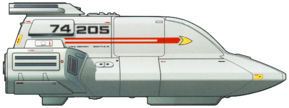
10.2.3 TYPE-18 SHUTTLEPOD Type:
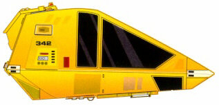
Medium short-range sublight shuttle. Developed in the mid-2360s, the Type-18 Shuttlepod is somewhat of a departure from the traditional layout for ships of its size. In response to the growing threat of conflicts with various galactic powers bordering or near to the Federation, this shuttlepod was designed to handle more vigorous assignments that still fell into the short-range roles of a shuttlepods. Even with her parent vessel under attack, the Type-18 was designed to function in battle situations and could even be used as an escape vehicle should the need arise. Lacking a warp core, the pod is a poor choice for travel beyond several million kilometers. Ships of this type are seeing limited deployment on various border patrol and defensive starship classes, including the Defiant-, Sabre-, and Steamrunner-class.
10.2.4 TYPE-6 PERSONNEL SHUTTLECRAFT (UPRTD)
Type:
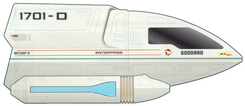
Light short-range warp shuttle. The Type-6 Personnel Shuttlecraft is currently in widespread use throughout Starfleet, and is only recently being replaced by the slightly newer Type-8 Shuttle of similar design. The Uprated version of this vessel is considered to be the ideal choice for short-range interplanetary travel, and its large size makes it suitable to transport personnel and cargo over these distances. A short-range transporter is installed onboard, allowing for easy beam out of cargo and crew to and from their destination. Atmospheric flight capabilities allow for this shuttle type to land on planetary surfaces. Ships of this type are currently in use aboard virtually every medium to large sized starship class, as well as aboard stations and Starbases. The Type-6 is perhaps the most successful shuttle design to date, and its overall structure and components are the foundations upon which the Type-8, -9, and -10 spaceframes are based. Major technological advancements in the 2370’s allowed for further upgrades to be made to the engine systems aboard shuttlecraft. These upgrades make this craft more capable of long-range spaceflight and, like its starship counterparst, no longer damages subspace.
10.2.7 TYPE-9 PERSONNEL SHUTTLECRAFT Type:
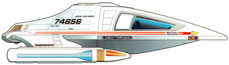
Medium long-range warp shuttle. The Type-9 Personnel Shuttle is a long-range craft capable of traveling at high warp for extended periods of time due to new advances in variable geometry warp physics. Making its debut just before the launch of the Intrepid-class, this shuttle type is ideal for scouting and recon missions, but is well suited to perform many multi-mission tasks. Equipped with powerful Type-VI phaser emitters, the shuttle is designed to hold its own ground for a longer period of time. Comfortable seating for four and moderate cargo space is still achieved without sacrificing speed and maneuverability. As is standard by the 2360’s, the shuttle is equipped with a medium-range transporter and is capable of traveling through a planet’s atmosphere. With its ability to travel at high-warp speeds, the Type-9 has been equipped with a more pronounced deflector dish that houses a compact long-range sensor that further helps it in its role as a scout. The Type-9 is now being deployed throughout the fleet and is especially aiding deep-space exploratory ships with its impressive abilities.
10.2.10 TYPE-9A CARGO SHUTTLECRAFT (UPRTD)
Type:
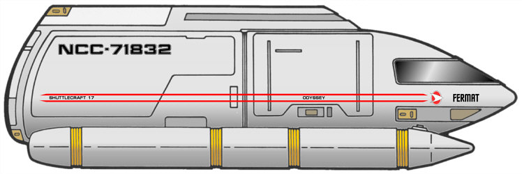
Heavy long-range warp shuttle. Short of a full-fledged transport ship, the Type-9A Cargo Shuttle is the primary shuttle of choice for cargo runs at major Starfleet facilities. Originally developed by the ASDB team stationed at Utopia Planitia, the 9A served as cargo vessel that carried components from the surface of Mars to the facilities in orbit. While able to travel at warp velocities, the 9A is somewhat slow at sub-light speeds, especially when carrying large amounts of cargo. The front of the shuttle is divided by a wall with a closable hatch, allowing for the aft area to be opened to the vacuum of space. The 9A also has the ability to carry one Sphinx Workpod in the aft area. A medium-range transporter and atmospheric flight capabilities allow it to easily complete its tasks. While rarely seen stationed aboard all but the largest starships, the Type-9A is a common site at any large Starfleet facility. In response to the need to transporter ground troops into areas heavily shielded, a variant designated the Type-9B was designed and is capable of carrying 40 troops and their equipment to the surface of a planet or interior of a space station. This variant has seen limited service onboard frontline ships, most notably the Steamrunner-class starship. Major technological advancements in the 2370’s allowed for further upgrades to be made to the engine systems aboard shuttlecraft. These upgrades make this craft more capable of long-range spaceflight and, like its starship counterparts, no longer damages subspace.
10.2.11 WORK BEE
Type:
Utility craft. The Work Bee is a capable stand-alone craft used for inspection of spaceborne hardware, repairs, assembly, and other activates requiring remote manipulators. The fully pressurized craft has changed little in design during the past 150 years, although periodic updates to the internal systems are done routinely. Onboard fuel cells and microfusion generators can keep the craft operational for 76.4 hours, and the life-support systems can provide breathable air, drinking water and cooling for the pilot for as long as fifteen hours. If the pilot is wearing a pressure suit or SEWG, the craft allows for the operator to exit while conducting operations. Entrance and exit is provided by the forward window, which lifts vertically to allow the pilot to come and go. A pair of robotic manipulator arms is folded beneath the main housing, and allows for work to be done through pilot-operated controls. In addition, the Work Bee is capable of handling a cargo attachment that makes it ideal for transferring cargo around large Starbase and spaceborne construction facilities. The cargo attachment features additional microfusion engines for supporting the increased mass.
Type:
Intrepid Class Integrated Craft Mounted on the underside of the saucer section, the Aerowing rests in a recessed hatchway just aft of the ventral sensor array. The craft serves in the capacity of a runabout aboard larger ships. In fact the Aerowing’s technology and design is based, in large part, on the Danube class runabout. The Aerowing provides a large secondary craft, long-range travel, and the protection, armament, and sensor capabilities beyond that of a standard auxiliary shuttle. Facilities include two sleeping bunks and a standard runabout passenger cabin. A replicator and flight couches provide for the needs of the passengers and a two-person transporter allows for beaming of personnel or cargo when needed. Atmospheric flight capabilities allow this shuttle type to land on planetary surfaces.
Operations aboard an Intrepid class starship fall under one of three categories: Flight Operations, Primary Mission Operations or Secondary Mission Operations. Flight Operations are all operations that relate directly to the function of the starship itself, which include power generation, starship upkeep, environmental systems, and any other system that is maintained and used to keep the vessel space worthy. Primary Mission Operations entail all tasks assigned and directed from the Main Bridge, and typically require full control and discretion over ship navigation and ship's resources. Secondary Mission operations are those operations that are not under the direct control of the Main Bridge, but do not impact Primary Mission Operations. Some examples of secondary mission operations include long-range cultural, diplomatic, or scientific programs run by independent or semi-autonomous groups aboard the starship.
Seeking out new worlds and new civilizations is central to all that Starfleet stands for. As something of a younger sister of the Galaxy class, Intrepids turn their impressive technology and speed to the business of pushing back the veil of the unknown. Mission for an Intrepid class starship may fall into one of the following categories, in order of her strongest capable mission parameter to her weakest mission parameter.
The normal flight and mission operations of the Intrepid class starship are conducted in accordance with a variety of Starfleet standard operating rules, determined by the current operational state of the starship. These operational states are determined by the Commanding Officer, although in certain specific cases, the Computer can automatically adjust to a higher alert status. The major operating modes are:
During Cruise Mode, the ship’s operations are run on three 8-hour shifts designated Alpha, Beta, and Gamma. Should a crisis develop, it may revert to a four-shift system of six hours to keep crew fatigue down. Typical Shift command is as follows: Alpha
Shift – Captain (CO)
Intrepid class vessels are capable of atmospheric entry and egress with equipment worked into the physical design of the starship. Each vessel is equipped with anti-gravity generators as well as impulse and RCS lifters strategically placed at the mass and stress points on the bottom portion of the engineering section. During Blue Alert, the Intrepid class lowers the projection sphere of the deflector shields and assumes an angle of attack perpendicular to the angular rotation of the planetary body if it has an atmosphere. This allows the vessel’s shape to work as a lifting body with air traveling under the broad and flat saucer and under the wing-like nacelle struts. Once in the atmosphere, navigation is controlled with RCS thrusters and use of the aft impulse engines. It is standard procedure to lower the landing gear at approximately 2500m above the Landing Zone (LZ) surface, regardless of LZ altitude. This minimizes the drag on the vessel. Once prepared for landing, Aft impulse engines are shut down and four vents on the ventral hull are opened. These vents cover the ventral impulse thrust plates. Impulse engines in miniature, the thrust plates serve only to provide lift to the Intrepid class as the anti-gravity generators effectively reduce its weight. The RCS thrusters provide final maneuvering power. Once on the ground, crew or equipment can be transported to the surface from the vessel, or use the ship’s turbolift system that connects to channels inside the landing struts themselves, and open out near the ‘feet’. Take-off is done in reverse.
Though
much
of a modern
starship’s systems are automated, they do require regular
maintenance and
upgrade. Maintenance is typically the purview of the Engineering, but
personnel
from certain divisions that are more familiar with them can also
maintain
specific systems. Systems
Diagnostics 11.1 EMERGENCY MEDICAL OPERATIONS Pursuant to Starfleet General Policy and Starfleet Medical Emergency Operations, at least 25% of the officers and crew of the Intrepid class are cross-trained to serve as Emergency Medical Technicians, to serve as triage specialists, medics, and other emergency medical functions along with non-medical emergency operations in engineering or tactical departments. This set of policies was established due to the wide variety of emergencies, both medical and otherwise, that a Federation Starship could respond to on any given mission. The Mess Hall on Deck 2 can serve as emergency intensive care wards, with an estimated online timeframe of 30 minutes with maximum engineering support. Cargo Bays 1 and 2 also provide additional space for emergency triage centers and recovery overflow. Portable field emitters can be erected for contagion management.
11.2 EMERGENCY MEDICAL HOLOGRAM Pursuant to new Medical Protocols, all Medical Facilities are equipped with holo-emitters for the emergency usage of the Emergency Medical Hologram System. Starships of this type were the first to carry the EMH Mark-I. Standard refit and rotation keeps their EMH up to date with the latest builds.
Pods are located on almost all decks. Each pod can support a total of eighty-six person-days (meaning, one person can last eighty-six days, two can last for forty-three, etc.). Two pods are reserved for the top four officers in the chain of command on the Intrepid class, because they are the last four to leave the ship. These are located on Deck 1, just aft of the bridge. As the number of experienced Captains dwindles in Starfleet, the notion of a Captain going down with his ship has been abolished. If the ship is abandoned, the top four officers in the chain of command will wait until everyone else is off the ship, opt to arm the auto-Destruct (not always necessary, but there if needed), and then leave in the two escape pods. The current lifepods are called ASRVs, or autonomous survival and recovery vehicles. The first group of these was delivered in 2337 to the last Renaissance class starship, the USS Hokkaido. In situations when the base vessel is not near a habitable system, up to four ASRVs may be linked together in a chain at junction ports to share and extend resources. In extreme circumstances or where additional capability is required, the entire bridge module of the Intrepid class starship can be ejected and maneuver away on it’s own thrusters. Since this is more time consuming than ejecting pods, this procedure is reserved only for situations where time is not critical.
11.4 RESCUE AND EVAC
OPERATIONS Rescue and Evacuation Operations for an Intrepid class starship will fall into one of two categories - abandoning the starship, or rescue and evacuation from a planetary body or another starship. Rescue Scenarios Resources are available for rescue and evacuation to Intrepid class starship include:
Abandon-Ship Scenarios Resources available for abandon-ship scenarios from an Intrepid class starship include:
Though rare, starships occasionally face the horrible concept of a warp core breech. As the primary power source for a starship, the explosive power of a warpcore far surpasses the superstructure and structural integrity field strengths and most often ends in the complete destruction of the starship and anything within a 20km blast radius. Modern starships have been equipped for this possibility and have the capability to eject their warpcore. The Intrepid class has an ejection port on the forward side of the ventral engineering hull. Magnetic rails inside the channel accelerate the core once disengaged from the ship and ‘fires’ it as far as 2000 meters away from the ship. The ship then moves away from the core as fast as possible under impulse power. Should the core not go critical, the Intrepid class can recover its warpcore by use of tractor beams and careful manipulation. Secondary Core: Emergency ejection of the backup warp core is all but unheard of since the core is never brought online in its storage slot. When in use in the primary core tube, ejection is identical.
APPENDIX
A - VARIANT DESIGNATIONS
E-AI – Light Explorer
APPENDIX
B - BASIC
TECHNICAL SPECIFICATIONS
ACCOMMODATION Officers
and Crew: 168 DIMENSIONS Overall
Length: 342.5
meters PERFORMANCE Full
Impulse: .25c ARMAMENT 11 Type-X phasers, 2 forward photon torpedo launchers, 2 aft torpedo launchers TRANSPORT EQUIPMENT Auxiliary Craft
Shuttlecraft
Transporters
Legend Deck 2: Officer's Mess, Senior Officers and VIP Quarters, Executive Officer’s Office Labs and Storage, Upper Sensor Platform Subsystems, Escape Pod Access Deck 3: Captain's Quarters, Officers' Quarters, and VIP Quarters, Equipment Storage, Torpedo Loading Maintenance, Testing Isolation Chamber, and Turbolift Maintenance. Deck 4: Crew quarters, Transporters Rooms (2 – 1P/S), Aft Photon Torpedo Launchers, Phaser Maintenance, Forward Sensor Pallet Subsystems, and Escape Pod Access Deck 5: Sickbay, Primary Sickbay Support Systems (ICU, Biohazard Support, Radiation Treatment Wards, Surgical Ward, Critical Care, Null-Gravity Treatment, Isolation Suites, etc.), Chief Medical Officer's Office, Counselor's Office, Crew Quarters, Library, Transporter Pattern Buffers (2 - 1 P/S), Holodecks (2 – 1P/S), Sensor Gear, Escape Pod Access, and Deck 6: Crew Quarters, Non-Specific Science Laboratories (8 – 5P/3S) Aux Deflector Control, Aux Computer Core, Escape Pod Access, Deck 7: Aux. Computer Core, Upper Cargo Bays 1 & 2, Labs, Escape Pod Access, RCS Thruster Access Deck 8: Astrometrics, Chief Science Officer’s Office, Deuterium Processing, Port/Starboard/Forward Docking Ports, ODN/EPS Main Trunks, Lower Cargo Bays 1 & 2 Deck 9: Cargo Loading Doors, Aerowing Shuttle Dock, and Labs Engineering
Section Deck 7: Deuterium Tankage, Warp Engine Core Injector Access Deck 8: Deuterium Tankage, Upper Premix Chamber, And Aft Work Pod Storage Deck 9: Cargo Loading Doors, Upper Aerowing Shuttle Dock, and Labs Deck 10: Main Shuttlebay, Shuttlebay Storage (SB2), Flight Control Center, Aft EV Access Airlock, Main Computer Core, Forward Photon Torpedo Launchers, Reserve Warp Engine Core, And Main Navigational Deflector Deck 11: Main Engineering, Engineer's Office, Aft Lounge, Warp Core, Auxiliary Warp Engine, Main Computer Core, Main Navigational Deflector Deck 12: Environmental Control, Antimatter Tankage, Main Deflector Control Systems Deck 13: Warp Engine Core, Labs, Escape Pod Access, And Secondary ODN/EPS Trunks Deck 14: Antimatter Processing, Aft Tractor Beam Emitter, Tractor Beam Subsystems, Escape Pod Access, and Ground Hover Footpad Systems Deck 15: Antimatter Loading Port, Forward Tractor Beam Emitter, Tractor Beam Subsystems, Plasma Relay Control Rooms, and Ground Hover Footpads
Love the show or hate it, Star Trek: Voyager presented fans with one of the coolest ships in Trek history, jam packed with new goodies that tech guys like myself drool over. Controversy has surrounded this ship; through creative writing changing it’s capabilities occasionally. I’ve tried to find a happy medium. I thought Voyager carried fewer torpedoes than that? Well that question has been hotly debated with people possessing far more time for debate than I possess. The number of torpedoes mentioned on screen was just over thirty I believe, with people taking the time to count them by episode and coming up with a figure that surpasses that number. The most obvious solution is that Voyager must have facilities aboard to produce more, at least the casings if not the warheads. Plus, given the size, other technological levels, and general armament of the class, I thought 50+ torps seemed more reasonable. She’s packed to the gills inside with Shuttles eh? Absolutely not. I know it’s a popular joke, but given the parameters of the show, you can hardly fault the producers for wanting shuttles to fly around in and blow up for the sake of drama. Currently her load out is seven shuttles, which is a respectable amount for a ship this size and the displayed size of her shuttlebays. It might seem heavy, but remember the “Shuttlebay 2” constantly mentioned in the show? It’s a bay equal to Shuttlebay 1, but behind it. Given the space seen in the first, I have no problem conceiving an almost equal number of shuttles being stored in the inner bay. Does it use Bio-Neural Gelpaks? Absolutely. The Intrepid class is the first of the advanced ships to utilize the Bio-Neural Gelpak technology. These packs are distributed throughout the ship to speed processing with ‘fuzzy logic’ thought done by engineered neural fibers. How
come the
Intrepid can land? Does it carry Borg tech? No, and thankfully so. I don’t personally like to see Trek ships glowing green :). No, the Borg stuff stays with Voyager; with the exception of whatever sensor/computer upgrades went into Astrometrics, which is detailed above.
APPENDIX
E - CREDITS
AND COPYRIGHT INFORMATION
INTREPID-CLASS SPECIFICATIONS CREATED BY: Kurt Goring SOURCES USED:
Copyright 2001 - Star Trek : A Call to Duty. Use of these specifications is restricted to the Star Trek: A Call to Duty (ST:ACTD) Technical Specifications domain at http://techspecs.acalltoduty.com and may only be reproduced with the express permission of the ST:ACTD on sites that clearly serve to provide information on ST:ACTD, its various ships and stations, or other related topics. Editing the contents of the information present on this page or reformatting the way in which it is presented is not permitted without the direct permission of ST:ACTD. Wherever possible, published sources were consulted to add to the wealth of knowledge in this document, and in some cases, this text was reproduced here. Sources used are properly cited in the "Credits and Copyright Information" appendix. No copyright infringement is intended.
|


|
|
|
|
 Copyright 2001 -
Star Trek
:
A Call To Duty, all rights reserved (herein referred to as the
'ST:ACTD'). STAR TREK and related marks, symbols, and
materials are trademarks of Paramount Pictures Corporation.
Unless noted otherwise, all material on this website, including but not
limited to images, audio, and text material (collectively the
"Material"), is protected by copyright owned or controlled by the
ST:ACTD, unless otherwise indicated. UNAUTHORIZED COPYING,
REPRODUCTION, REPUBLISHING, UPLOADING, DOWNLOADING, POSTING,
TRANSMITTING OR DUPLICATING OF ANY OF THE MATERIAL WITHOUT EXPRESS
PERMISSION IS PROHIBITED. Copyright 2001 -
Star Trek
:
A Call To Duty, all rights reserved (herein referred to as the
'ST:ACTD'). STAR TREK and related marks, symbols, and
materials are trademarks of Paramount Pictures Corporation.
Unless noted otherwise, all material on this website, including but not
limited to images, audio, and text material (collectively the
"Material"), is protected by copyright owned or controlled by the
ST:ACTD, unless otherwise indicated. UNAUTHORIZED COPYING,
REPRODUCTION, REPUBLISHING, UPLOADING, DOWNLOADING, POSTING,
TRANSMITTING OR DUPLICATING OF ANY OF THE MATERIAL WITHOUT EXPRESS
PERMISSION IS PROHIBITED. |
||