
Nebula-Class Explorer
UNITED FEDERATION OF PLANETS: STARFLEET DIVISION
Advanced Technical Specifications for the Nebula-Class Production Vehicle

|
Accommodation: 750 (200 officers, 550 enlisted), plus 130 visiting personnel Classification: Explorer [Explorer/Defensive/Diplomatic] Funding for Nebula Class Development Project Provided by: Advanced Starship Design Bureau, United Federation of Planets Defense Council Development Project Started: 2343 Production Start Date: 2353 Production End Date: Still in Production Current Status: In Service |
Locations of Nebula-Class Construction:
Current Starship Identification and Registration Numbers:
|
Pursuant to Starfleet Exploration Directive 902.3, the following objectives have been established for an Nebula Class Starship:
Provide a mobile platform for a wide range of ongoing scientific and cultural research projects.
Replace aging Ambassador, Oberth and Excelsior class Starships as primary instruments of Starfleet’s exploration programs.
Provide autonomous capability for full execution of Federation defensive, cultural, scientific, and explorative policy in deep space or border territory.
Serve as a frontline support vehicle during times of war and emergencies.
Provide a mobile platform for testing and implementation of mission-specific or new technology of any kind.
Length:
442.23
meters
Width: 318.11
meters
Height: 130.43
meters
Weight: 3,309,000 metric tonnes
Cargo capacity: Dependant upon mission type
Hull:
Duranium-Tritanium
composite
Number of Decks: 30
The Nebula-class was developed along-side the Galaxy-class in the 2340s and ‘50s. While Starfleet firmly believed in the feasibility of the Galaxy-class, they wanted a more cost-effective ship that would be able to perform much of the same missions as the larger, more expensive capital ships under construction.
Part of the design that was approved by Starfleet included a multi-mission module that could easily be exchanged within days at a certified facility. The first of which consisted of a sensor dome attached to the rear of the ship. Designed to aid in long-range reconnaissance and search-and-rescue operations, the sensor pod quickly proved its usefulness, so much so that several Nebula-class vessels were allocated to border patrols.
With the flexibility given to it by the replaceable pod-module, the Nebula-class has quickly become one of the most produced and utilized starships of the 24th century.
Shortly after the Galaxy Class Project was approved in 2343, it was realized that the expense of building such a large capital ship, both in resources and time, would limit the number of ships being constructed. Starfleet, however, was impressed with the design of the Galaxy-class, and wished to adapt it for use in a smaller, less expensive class of starships. In 2345, the Nebula Class Project was officially approved after designers worked for nearly seven months side-by-side with the Galaxy Class Project team at the ASDB.
The Nebula-class proposal used the same basic design as the Galaxy, with two major differences: the stardrive section was approximately 12 decks shorter than the Galaxy’s, and the warp nacelles were situated facing “downward” as opposed to the “upward” placement on the Galaxy.
Another design incorporated into the Nebula Class Project was the “rollpod” used in previous classes, such as the Miranda. In fact, as the prototype USS Nebula was being built, one of the chief designers referred to it as a “24th Century Miranda,” a nickname that would later be transferred to the Akira Class Project.
By leaving seventy-percent of the interior unfinished, the USS Nebula was able to leave the Utopia Planitia construction yards – minus the roll-pod – under her own power in late 2353. Around that time the Akira Class Project was approved, and some of the design team members were transferred to that Project.
Starfleet did not feel the need to have two starships with “rollpods”, and wished to try something different with the Nebula Class. The multi-mission modules used on the New Orleans class vessels had proven useful, and a variant was designed for the Nebula. The original module was ellipitcally-shaped and connected to the stardrive section by the use of two support pylons. The design proved sound, and when equipped with specialized sensor pallets it greatly increased the range of the Nebula’s sensors.
The original module design, however, would not last more than a decade. Years after the debut of the ellipitical pod, reports were received claiming that micro-fractures had developed in the support pylons connecting the pod to the ship while at high-warp for durations longer than 48 hours. All Nebula-class ships were restricted to a speed of warp factor five, or warp seven under extreme emergencies, until the problem could be resolved.
The replacement pod came in the form of a triangular module, connected to the stardrive section by a single pylon. This design, however, partially blocked the main shuttlebay, making docking and launching of shuttles difficult. The second shuttlebay, located on deck 22, was expanded to carry more auxiliary craft and act as the primary launchpad for shuttle craft.
General Overview: Primary operational control of the Nebula-class is provided by the Main Bridge, located at the top of the primary hull on Deck 1. The Main Bridge directly supervises all primary mission operations and coordinates all departmental activities. Designated as an emergency environmental support shelter, Deck 1 receives priority life support from two protected utilities trunks.
The Main Bridge is an ejectable module, allowing for a wider variety in mission parameters.
Layout: The standard Bridge is normally configured to match that of Galaxy-class bridges, with the central area providing seating and information displays for the Captain and two other officers. The Captain’s Chair includes consoles which can be used to control almost any aspect of the ship. The two Officer seats are equipped with fully programmable consoles for a variety of uses.
Directly ahead of the command area are the consoles for flight control and operations.
The Flight Control console, often referred to as Conn, is responsible for the actual piloting and navigation of the spacecraft. Although these are heavily automated functions, an officer is responsible for overseeing these operations at all times. The conn officer also works as the bridge liasion to engineering.
The Operations console (OPS) is used to continually track and coordinate resources aboard the ship. During alert situations, OPS is responsible for supervision of power allocation in coordination with the Engineering department. For example, shutting down holodecks to conserve power during alert situations. The Operations Officer is also in charge of assigning gear to Away Team members.
At the very front of the bridge chamber is a large viewscreen. This main viewer performs all the standard duties expected of it. New ships being constructed are having their viewscreens replaced with a holographic viewer system, as debuted on the Sovereign-class. Older ships are being refitted as time and resources allow. The holographic viewer system is normally deactivated, displaying the bulkhead, but can be activated at a moment’s notice to display one of several things: From a subspace message to the results of a sensor scan.
The Main Bridge station dedicated to defensive/offense systems control and starship internal security is Tactical, which is located directly behind the command chairs. The physical layout of the raised tactical station console describes a sweeping curve affording an unobstructed view of the main viewer, and an equally clear view of the command stations below. This allows for an uninterrupted exchange between the Tactical Officer and other bridge officers during critical operations. The console lacks a seat and is therefore a standup position, deemed ergonomically necessary for efficient security functions. While the length of the control/display panel can accommodate two officers, most scenarios will see a single tactical officer conducting operations alone.
Science stations I and II are the first two aft stations located directly behind the Tactical station on the upper level of the Main Bridge. They are used by bridge personnel to provide real-time scientific data to command personnel.
Science II has access to all science, navigational, sensor, and communications systems. Science II can be configured to operate in tandem with Science I, although security links and all other non-science data is withheld from Science II. Science II usually works independently of Science I.
Next to the two science stations is the engineering console. This console has a small cutaway diagram of the ship, which displays all engineering-relevant data and shows warp fields and engine output. This console also has priority links to the computers, the WPS (Warp Propulsion System), the IPS (Impulse Propulsion System), navigation, Structural Integrity Field (SIF), and Inertial Dampening Field (IDF). Although usually unattended, the Chief Engineer can bring this console to full Enable mode by entering voice codes and undergoing a retinal scan. Directly aft of this console is the Engineering II console, which is fully programmable to run any Secondary Console function, including Sciences, Medical, Operations, Limited Helm control, or Security.
This console, as does every console on the bridge, also has the hand-input sub-console for use in setting the auto-destruct of the ship. The auto-destruct sequence follows Standard Starfleet security procedures which can be accessed via any secured Memory Alpha ODN connection.
There are two main turbolifts on the bridge that can handle normal transit around the ship. There is an emergency ladder that can be used to evacuate the Bridge. Also accessible from the Bridge is the Observation Lounge, Crew Head and the Captain’s Ready Room. A third turbolift, used to ferry crew to the Battle Bridge on Galaxy-class ships, is normally programmed to transport bridge officers to Main Engineering in an emergency. As such, all other turbolifts are cleared from its path, and the turbolift operates at a highly increased speed. It can be a nauseating experience for crew members who are not accustomed to it.
Main Engineering is located on Deck 24, and serves as the master control for the ship’s warp propulsion system, as well as the impulse propulsion system and other engineering systems.
During emergencies Main Engineering can be turned into a command and control center by converting a number of consoles to duplicate the stations on the Bridge. The software is already preloaded onto these consoles and each vessel has specific proceedures in place should a situation present itself.
There are three main consoles in Engineering, the Master Systems Monitor, Warp Propulsion System (WPS) console, and Impulse Propulsion System (IPS) console. In between the WPS & IPS console is the Master Systems Display. Heading towards the warp core from the main entrance one will find the Chief Engineer's Office on the left and the Assistant Chief Engineer's console on the right. A little more forward is the isolation door. Access to the upper level of Engineering can be found by a ladder on the left of the Matter/Antimatter Reaction Chamber (M/ARC) or an elevator on the right. The upper level has access to many auxilary systems as well as egress points.
Phaser array arrangement: Primary hull: Three dorsal phaser arrays on the primary hull, one primary dorsal array extending 340 degrees and two point defense arrays to either side of the Shuttlebay. The arrays cover the entire semi-sphere above the ship, except for a few blind spots close to the hull and Shuttlebay. One ventral phaser array located on the primary hull extends approximately 320 degrees and covers the forward and lateral portions of the semi-sphere below the ship, except for those blind spots close to the hull. Total of 4 phaser arrays on primary hull.
Secondary hull: One phaser array on each nacelle pylon provides coverage on either side of the ship. A single point defense array near the aft torpedo launcher provides defense to the aft of the ship. A phaser array on the ventral side of the ship provides coverage to areas below the ship. Total of 4 phaser arrays on secondary hull.
When the weapons pod is installed, there are three phaser arrays located on the module itself to provide additional protection.
Phaser Array Type: The Nebula-class vessel utilizes the Type X phaser array system. The eight arrays are all type X, the new standard emitter. Each array fires a steady beam of phaser energy, and the forced-focus emitters discharge the phasers at speeds approaching .986c (which works out to about 182,520 miles per second - nearly warp one). Current Tactical policy has phaser arrays automatically rotate phaser frequency and attempt to lock onto the frequency and phase of a threat vehicle's shields for shield penetration.
Phaser Array Output: Groups of emitters are supplied by redundant sets of energy feeds from the primary trunks of the electro plasma system (EPS). Individually, each type X-emitter can only discharge approximately 5.1 MW (megawatts). However, several emitters can direct their fire onto one target area to increase damage throughput.
Phaser Array Range: Maximum effective range is 300,000 kilometers.
Primary purpose: Assault
Secondary purpose: Defense/anti-spacecraft/anti-fighter
Arrangement: Two torpedo launchers, one located just above the main deflector dish and another at the rear of the ship above the impulse engine, provide the Nebula-class with additional defense and offense capabilities. These launchers are identical to the launchers found in such capital ships as the Galaxy-class, and hence have the capability of firing up to ten torpedoes at one time, with a reload time of six seconds.
Type: Mark XXV photon torpedo, capable of pattern firing (sierra, etc.) as well as independent launch. Standard explosive yield is rated at 18.5 isotons. Some ships also carry a small complement of quantum torpedoes, each with an explosive yield of approximately 50 isotons. Quantum torpedoes are not standard equipment on Federation starships. Tri-cobalt devices are also not standard equipment.
Payload: A Nebula-class vessel can carry a maximum of 250 torpedo casings, with approximately 25% of those casings (63) dedicated to sensor probes. When outfitted with the weapons pod, the number of torpedo casings carried increases to 450 in number.
Range: Maximum effective range is 3,000,000 kilometers. Maximum range before fuel exhaustion is 3,500,000 kilometers.
Primary purpose: Assault
Secondary purpose: Anti-spacecraft
Type: Symmetrical subspace graviton field. This type of shield is fairly similar to those of most other starships. Under Starfleet Directives all vessels incorporate the nutation shift in frequency. During combat, the shield sends data on what type of weapon is being used on it, and what frequency and phase the weapon uses. Once this is analyzed by the tactical officer, the shield can be configured to have the same frequency as the incoming weapon - but different nutation. This tactic dramatically increases shield efficiency.
Output: There are ten shield generators on a Nebula-class starship, each generating a field of 384 MW in amplitude. During alert situations, up to six shield generators can operate in parallel phase-lock, providing a continuous output of approximately 2,304 MW. Peak momentary load of a single generator has been rated at 473,000 MW for periods approaching 170 milliseconds.
Range: The shields, when raised, operate at two distances. One is a uniform distance from the hull, averaging about 10 to 12 meters. The other is a bubble field, which varies in distance from any single point on the hull but has a common center within the ship.
Primary purpose: Defense from enemy threat forces, hazardous radiation and micro-meteoroid particles.
Secondary purpose: Ramming threat vehicles.
Number of computer cores: Three; Any of these three cores is able to handle the primary operational computing load of the entire vessel. Two of the cores are located near the center of the Primary Hull between Decks 5 and 14 (one on the port side, one on the starboard), while the third is located in the Engineering Hull between Decks 18 and 25.
Type: The computer cores on Nebula-Class starships are isolinear storage devices utilizing faster than light processing drives with isolinear temporary storage. Cooling of the isolinear core is accomplished by a regenerative liquid nitrogen loop.
Access to all Starfleet data is highly regulated. A standard set of access levels have been programmed into the computer cores of all ships in order to stop any undesired access to confidential data.
Security levels are also variable, and task-specific. Certain areas of the ship are restricted to unauthorized personnel, regardless of security level. Security levels can also be raised, lowered, or revoked by Command personnel.
Security levels normally in use aboard a Federation starship are:
- Level 10 – Captain and Above
- Level 9 – First Officer
- Level 8 - Commander
- Level 7 – Lt. Commander
- Level 6 – Lieutenant
- Level 5 – Lt. Junior Grade
- Level 4 - Ensign
- Level 3 – Non-Commissioned Crew
- Level 2 – Civilian Personnel
- Level 1 – Open Access (Read Only)
Note: Security Levels beyond current rank can and are bestowed where, when and to whom they are necessary.
The main computer grants access based on a battery of checks to the individual user, including face and voice recognition in conjunction with a vocal code as an added level of security.
All Starfleet vessels make use of a computer program called a Universal Translator that is employed for communication among persons who speak different languages. It performs a pattern analysis of an unknown language based on a variety of criteria to create a translation matrix. The translator is built in the Starfleet badge and small receivers are implanted in the ear canal.
The Universal Translator matrix aboard Federation starships is updated periodically as new dialects are encountered.
Type: TPG Matter/Anti-Matter Reaction Drive, developed by Theoretical Propulsion Group in conjunction with the Advanced Starship Design Bureau - Utopia Planitia Division. Information on this Warp Drive is classified [repealed: 2371; now available in standard Starfleet Omnipedia Databases].
Normal Cruising Speed: Warp 6
Cruising Speed as pursuant to Warp Limitations, as a cause of subspace pollution: Warp 5
Maximum Speed: Warp 9.6 for 12 hours
Note: Vessels equipped with the TPG M/ARA Drive System no longer have the maximum cruising speed limit of Warp 5, thanks to innovations discovered and utilized in the General Electric Type 8 M/ARA Warp Drive outfitted in the new Sovereign Class Starship. Pursuant to Starfleet Command Directive 12856.A, all Starships will receive upgrades to their Warp Core system to prevent further pollution of Subspace.
Type: Nebula-class starships use slightly modified impulse engines of the type found on Galaxy-class ships. The main impulse engine is located on deck 16 on the rear of the connection pylon, just above the secondary shuttle bay. There are also two smaller secondary engines located on the saucer section, located on deck 10.
Output: The main engine can propel the ship at speeds just under .75c. Full impulse is 0.25c, with half-impulse being 0.125c and one-quarter impulse being 0.0625c. Maximum impulse is .994c (one tenth away from 186,282 miles per second, which is warp one), and requires the saucer engines providing additional power. Standard impulse operations are limited to .25c, due to time dilation problems.
Type: Standard magnetohydrodynamic gas-fusion thrusters, identical to those found on Galaxy-class starships. There are 14 reaction control thrusters on a Nebula-class starship.
Output: Each thruster quad can produce 5.5 million Newtons of exhaust.
6.0
UTILITIES AND AUXILIARY SYSTEMS ![]()
The main deflector dish is located along the forward portion of the secondary hull, and is located just forward of the primary engineering spaces. Composed of molybdenum/duranium mesh panels over a duranium framework, the dish can be manually moved 7.2 degrees in any direction off the ship's Z-axis. The main deflector dish's shield and sensor power comes from three graviton polarity generators located on deck 24, each capable of generating 128 MW which fed into a pair of 550 millicochrane subspace field distortion amplifiers.
Type: Multiphase subspace graviton beam, used for direct manipulation of objects from a submicron to a macroscopic level at any relative bearing to the ship. Each emitter is directly mounted to the primary members of the ship's framework, to lessen the effects of isopiestic subspace shearing, inertial potential imbalance, and mechanical stress.
Output: Each tractor beam emitter is built around three multiphase 15 MW graviton polarity sources, each feeding two 475 millicochrane subspace field amplifiers. Phase accuracy is within 1.3 arc-seconds per microsecond, which gives superior interference pattern control. Each emitter can gain extra power from the SIF by means of molybdenum-jacketed waveguides. The subspace fields generated around the beam (when the beam is used) can envelop objects up to 920 meters, lowering the local gravitational constant of the universe for the region inside the field and making the object much easier to manipulate.
Range: Effective tractor beam range varies with payload mass and desired delta-v (change in relative velocity). Assuming a nominal 15 m/sec-squared delta-v, the multiphase tractor emitters can be used with a payload approaching 116,380,000,000 metric tons at less than 2,000 meters. Conversely, the same delta-v can be imparted to an object massing about one metric ton at ranges approaching 30,000 kilometers.
Primary purpose: Towing or manipulation of objects
Secondary purpose: Tactical; pushing enemy ships into each other.
Number
of Systems:
12
Personnel
Transporters:
4 (Transporter Rooms 1-4)
Cargo
Transporters:
4
Emergency
Transporters (Beam-Out only):
4
Range:
40,000 kilometers
Personnel Transporters:
Cargo Transporters:
Emergency Transporters:
Further information regarding the theory and operation of transporters is available from any Starfleet Omnipedia Database.
Standard
Communications Range: 42,000 - 100,000 kilometers
Standard Data Transmission Speed: 18.5 kiloquads per
second
Subspace Communications Speed: Warp 9.9997
7.0
SCIENCE AND REMOTE SENSING SYSTEMS ![]()
Long range and navigational sensors are located behind the main deflector dish, to avoid sensor "ghosts" and other detrimental effects consistent with main deflector dish millicochrane static field output. Lateral sensor pallets are located around the rim of the entire starship, providing full coverage in all standard scientific fields, but with emphasis in the following areas:
Astronomical phenomena
Planetary analysis
Remote life-form analysis
EM scanning
Passive neutrino scanning
Parametric subspace field stress (a scan to search for cloaked ships)
Thermal variances
Quasi-stellar material
Each sensor pallet can be interchanged and re-calibrated with any other pallet on the ship.
This is an independent subspace graviton field-current scanner, allowing the ship to track vessels at high warp by locking onto the eddy currents from the threat ship's warp field, then follow the currents by using multi-model image mapping.
There are twenty-four independent tactical sensors installed on Nebula-class starships. Each sensor automatically tracks and locks onto incoming hostile vessels and reports bearing, aspect, distance, and vulnerability percentage to the tactical station on the main bridge. Each tactical sensor is approximately 84% efficient against electronic counter-measures (ECM).
The stellar cartography bay is situated on decks 9 and 10, with direct EPS power feed from Engineering. The Main Entrance is located on Deck 9, with maintenance shafts on decks 8 and 10. All information is directed to the bridge and can be displayed on any console or the main viewscreen. The large room contains highly-specialized holographic emitters which are capable of creating detailed representations of any region of space stored in the ship’s computer.
There are numerous science labs on a Nebula-class ship, and each can be configured to perform many different functions. The different science labs include bio-chem-physics labs, XT (extra-terrestrial) analysis labs, eugenic labs, astrophysics/astrometrics and stellar cartography labs.
A probe is a device that contains a number of general purpose or mission specific sensors and can be launched from a starship for closer examination of objects in space.
There are nine different classes of probes, which vary in sensor types, power, and performance ratings. The spacecraft frame of a probe consists of molded duranium-tritanium and pressure-bonded lufium boronate, with sensor windows of triple layered transparent aluminum. With a warhead attached, a probe becomes a photon torpedo. The standard equipment of all nine types of probes are instruments to detect and analyze all normal EM and subspace bands, organic and inorganic chemical compounds, atmospheric constituents, and mechanical force properties. All nine types are capable of surviving a powered atmospheric entry, but only three are special designed for aerial maneuvering and soft landing. These ones can also be used for spatial burying. Many probes can be real-time controlled and piloted from a starship to investigate an environment dangerous hostile or otherwise inaccessible for an away-team.
The nine standard classes are:


There are two facilities on Deck 12 that are used by the medical department to diagnose and treat ailments. The primary Sickbay facility, which is located on the port side of the saucer section, consists of two medical intensive-care wards, an attached laboratory, the Chief Medical Officer’s office, and a small nursery. The second facility, located on the starboard side, is similar to the primary sickbay but features two dedicated surgery suites, a physical therapy facility, a nursery and a null-grav therapy ward. Adjacent to the second facility is a dental care office and a full biohazard isolation unit.
Normal on-duty medical complement for alpha and beta shifts is one staff physician, two nurses and one medical technician. During the night shift, normal staffing drops to two nurses. Approximately 40% of all crew personnel are cross-trained for emergencies.
Aid Stations: Like on Starbases and other large ships, the Nebula Class has nurse stations scattered throughout the vessel at critical junctions. These areas are staffed on a rotating schedule during green mode, and during higher alert status they may all be activated. They provide first aid to injured personnel and become quick essential command posts during situations when the ship is damaged. When the Captain needs to know how many people are injured, those who find out serve at these stations. Aid stations are normally located on every other deck, however the exact configuration and number is adjustable, pursuant to the wishes of the CMO and CO.
General Overview: All crew and officers' quarters are located on decks 2, 3, 5-9, and 11-20.
Individuals assigned to the ship for periods over six months are permitted to reconfigure their quarters within hardware, volume, and mass limits. Individuals assigned for shorter periods are generally restricted to standard quarters configuration.
Crew Quarters: Standard Living Quarters are provided for both Starfleet Non-Commissioned Officers and Ensigns. These persons are expected to share their room with another crewmate due to space restrictions aboard the starship. After six months, crewmembers are permitted to bring family aboard the ship and a slightly larger room is allocated to them.
Two NCO's or two Ensigns are assigned to a suite. Accommodations include 2 bedrooms with standard beds, connected by a living/work area. A washroom with ultrasonic shower is located off of each bedroom. A food replicator and a personal holographic viewer are located in the living area. Small pets are allowed to NCO's.
Enlisted crewmembers share quarters with up to 4 others. Accommodations include 2 bedrooms with twin beds, connected by a living/work area. A washroom with ultrasonic shower is located off of each bedroom. A food replicator and a personal holographic viewer are located in the living area. Pets are not allowed to enlisted crew.
Crewmen can request that their living quarters be combined to create a single larger dwelling.
Officers' Quarters: Starfleet personnel from the rank of Ensign up to Commander are given one set of quarters to themselves (they do not need to share).
These accommodations typically include a small bathroom, a bedroom (with standard bed), a living/work area, a food replicator, an sonic shower, personal holographic viewer, and provisions for pets.
Officers may request that their living quarters be combined to form one large dwelling.
Executive Quarters: The Captain and Executive Officer of the ship both have special quarters, located on Deck 8.
These quarters are much more luxurious than any others on the ship, with the exception of the VIP/Diplomatic Guest quarters. Both the Executive Officer's and the Captain's quarters are larger than standard Officers’ Quarters, and this space generally has the following accommodations: a large bedroom, living/work area, bathroom, food replicator, sonic shower, old-fashioned water shower (if requested by the officer), personal holographic viewer, provisions for pets, and even a null gravity sleeping chamber (if requested).
VIP/Diplomatic Guest Quarters: Nebula-class starships are symbols of UFP authority, a tool in dealing with other races. The ship is easily configured for diplomatic missions, and the need to transport or accommodate Very Important Persons, diplomats, or ambassadors may arise.
These quarters are located on Deck 8. These quarters include a bedroom, spacious living/work area, personal viewscreen, sonic shower, bathtub/water shower, provisions for pets, food replicator, and a null-grav sleeping chamber. These quarters can be immediately converted to class H, K, L, N, and N2 environments.
General Overview: Nebula-class vessels are large starships designed for deep-space exploration and patrol, as well as extended missions. As such, crew morale is boosted by various recreational facilities.
Holodecks: There are four standard holodeck facilities on a Nebula-class vessel, all located on deck 11.
Holosuites: These are smaller versions of standard Federation Holodecks, designed for individual usage (the four Holodecks themselves are to be used by groups or individual officers; enlisted crewmen and cadets are not allowed to use the Holodecks under normal circumstances). They do everything that their larger siblings do, only these Holosuites can't handle as many variables and are less detailed. They are similar to the Holodecks on an Intrepid-class Starship. There are 20 Holosuites onboard, situated on decks 11 and 21.
Phaser Range: Sometimes the only way a Starfleet officer or crewman can vent his frustration is through the barrel of a phaser rifle. The phaser range is located on deck 15, next to the Armory.
Normal phaser recreation and practice is used with a type II phaser set to level 3 (heavy stun). The person stands in the middle of the room, with no light except for the circle in the middle of the floor that the person is standing in. Colored circular dots approximately the size of a human hand whirl across the walls, and the person aims and fires. After completing a round, the amounts of hits and misses, along with the percentage of accuracy is announced by the ship's computer.
The phaser range is also used by security to train ship's personnel in marksmanship. During training, the holo-emitters in the phaser range are activated, creating a holographic setting, similar to what a holodeck does. Personnel are "turned loose" either independently or in an Away Team formation to explore the setting presented to them, and the security officer in charge will take notes on the performance of each person as they take cover, return fire, protect each other, and perform a variety of different scenarios. All expeditions are visually recorded by the computer to be reviewed later by all involved parties. Doing so can reveal several weaknesses and errors in judgement, allowing marksmanship to improve upon successive tests.
All Starfleet and attached personnel receive instruction on the safe operation and use of a low-power variant of a Type I phaser (limited to setting 3). All Starfleet officers receive advanced training and are issued full-power Type I phasers as personal defensive arms.
Weight Room: Some Starfleet personnel can find solace from the aggravations of day-to-day life in exercising their bodies.
The weight room is located on deck 15, next to the phaser range. This weight room has full body building and exercise apparatuses available for your disposal; any kind of exercise can be performed here, be it Terran, Klingon, Vulcan, Bajoran, Trill, or others.
There is also a wrestling mat in the weight room, which can be used for wrestling, martial arts, kick-boxing, or any other sort of hand-to-hand fighting. There are holo-diodes along the walls and ceiling which generate a holographic opponent (if you can't find someone to challenge), trained in the combat field of your choice. The computer stores your personal attack and defense patterns as it gains experience on your style of fighting, and adapts to defeat you.
There are also racks of hand-to-hand combat weapons, for use in training. Ancient weapon proficiencies for Starfleet personnel are recommended; phasers may not always be available for use in contingencies. Terran, Klingon, Betazoid, Vulcan, Bajoran, and other non-energy weapons are available for training.
This is a large lounge, located on deck 10, forward. It has a very relaxed and congenial air about it; the "Ten-Forward Lounge" is the only place on the ship where rank means nothing - "sir" need not be uttered when a person of lower rank addresses an officer, and everyone is on an equal footing. Opinions can be voiced in complete safety. This lounge is the social center of the ship.
The Ten-Forward Lounge has a battery of recreational games and assorted "stuff". Pool tables, poker tables (complete with holographic dealer and chips, on some ships), windows that look out into space, heavily cushioned seats, and numerous other games. There is also a bar (with holographic bartender, on some ships), and it stores various potent alcoholic beverages, such as chech'tluth, Aldebaran whiskey, Saurian brandy, Tzartak aperitif, Tamarian Frost, C&E Warp Lager, Warnog, Antarean brandy, Romulan Ale, and countless others. The replicators are able to recreate almost any food or drink, and can be programmed with custom delicacies.
9.0
AUXILIARY SPACECRAFT SYSTEMS ![]()
The main shuttlebay is located on Deck 4, aft, and oversees flight operations for auxilliary spacecraft attached to the ship. The large shuttlebay contains six shuttlepods, as well as various shuttlecraft that can be used by flight-qualified personnel.
The main shuttlebay also contains equipment and spare parts to conduct repairs on damaged shuttles, and normally carries enough raw material to completely build two new shuttlecraft.
A second shuttlebay is located on deck 22 at the rear of the ship, just below the impulse engine.
Because of the position of the pod, most flight operations are conducted from the second shuttlebay. When a shuttle must be launched from the main shuttlebay, the ship is slowed to one-eighth impulse power, to allow for more precise maneuvering from the shuttle pilot.
Shuttlecraft
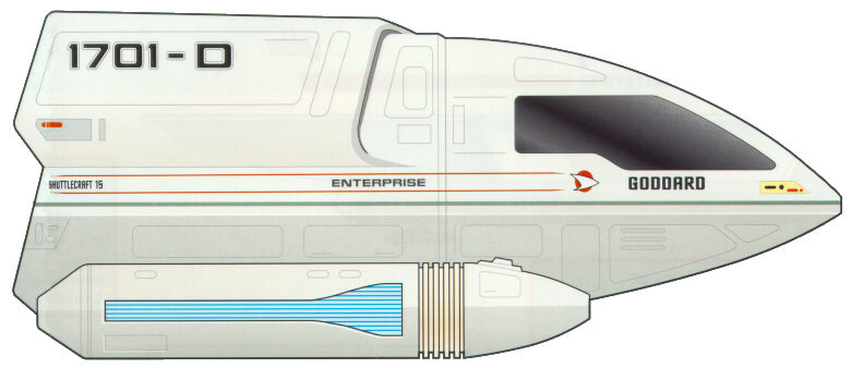
9.2.1 TYPE-15 SHUTTLEPOD

Type:
Light short-range sublight shuttle.
Accommodation: Two; pilot and system
manager.
Power Plant: Two 500 millicochrane impulse
driver engines, four RCS thrusters, three sarium krellide storage cells.
Dimensions: Length, 3.6 m; beam, 2.4 m;
height 1.6 m.
Mass: 0.86 metric tones.
Performance: Maximum delta-v, 12,800
m/sec.
Armament: Two Type-IV phaser emitters.
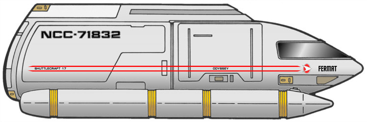
The Type-15 Shuttlepod is a two person craft primarily used for short-ranged transportations of personnel and cargo, as well as for extravehicular inspections of Federation starships, stations and associated facilities. Lacking the ability to obtain warp speeds, the Type-15 is a poor candidate for even interplanetary travel, and is traditionally used as a means of transport between objects only a few kilometers apart. The craft is capable of atmospheric flight, allowing for routine flights between orbiting craft or stations and planetside facilities. Ships of this type are stationed aboard various starship classes and stations, both spaceborne and planetside.
A variant of this type, the Type-15A Shuttlepod, shares the same specifications of its sister craft, but is capable of reaching a maximum delta-v of 13,200 m/sec. The Type-15A was a limited production craft and the information gained from its service allowed for further streamlining of what would eventually become the Type-16 Shuttlepod. Still, the 15A remains in active service, and existing Type-15 spaceframes can easily be converted to the 15A provided that off the shelf parts are available. However, it should be noted that Starfleet Operations has deemed that the 15A spaceframe exhausts its fuel supply rather quickly and its production at major assembly plants is now discontinued.
9.2.2 TYPE-16 SHUTTLEPOD
Type:
Medium short-range sublight shuttle.
Accommodation: Two; pilot and system
manager.
Power Plant: Two 750 millicochrane impulse
driver engines, four RCS thrusters, four sarium krellide storage cells.
Dimensions: Length, 4.8 m; beam, 2.4 m;
height 1.6 m.
Mass: 1.25 metric tones.
Performance: Maximum delta-v, 12,250
m/sec.
Armament: Two Type-IV phaser emitters.
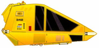
Like the Type-15, the Type-16 Shuttlepod is a two person craft primarily used for short-ranged transportations of personnel and cargo, as well as for extravehicular inspections of Federation starships, stations and associated facilities. Lacking the ability to obtain warp speeds, the Type-16 is a poor candidate for even interplanetary travel, and is traditionally used as a means of transport between objects only a few kilometers apart. The craft is capable of atmospheric flight, allowing for routine flights between orbiting craft or stations and planetside facilities, and its cargo capacity is slightly higher then that of the Type-15. Ships of this type are stationed aboard various starship classes and stations, both spaceborne and planetside.
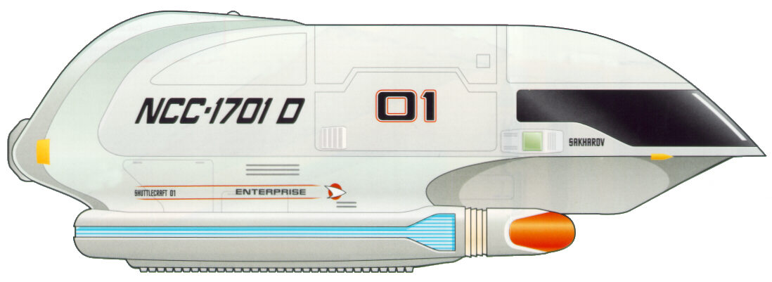
9.2.4 TYPE-6 PERSONNEL SHUTTLE (UPRTD)
Type:
Light short-range warp shuttle.
Accommodation: Two flight crew, six
passengers.
Power Plant: One 50 cochrane warp engine,
two 750 millicochrane impulse engines, four RCS thrusters.
Dimensions: Length, 6.0 m; beam, 4.4 m;
height 2.7 m.
Mass: 3.38 metric tones.
Performance: Sustained Warp 3.
Armament: Two Type-IV phaser emitters.
The Type-6 Personnel Shuttlecraft is currently in widespread use throughout Starfleet, and is only recently being replaced by the slightly newer Type-8 Shuttle of similar design. The Uprated version of this vessel is considered to be the ideal choice for short-range interplanetary travel, and its large size makes it suitable to transport personnel and cargo over these distances. A short-range transporter is installed onboard, allowing for easy beam out of cargo and crew to and from their destination. Atmospheric flight capabilities allow for this shuttle type to land on planetary surfaces. Ships of this type are currently in use aboard virtually every medium to large sized starship class, as well as aboard stations and Starbases.
The Type-6 is perhaps the most successful shuttle design to date, and its overall structure and components are the foundations upon which the Type-8, -9, and -10 spaceframes are based.
Major technological advancements in the 2370’s allowed for further upgrades to be made to the engine systems aboard shuttlecraft. These upgrades make this craft more capable of long-range spaceflight and, like its starship counterparst, no longer damages subspace.
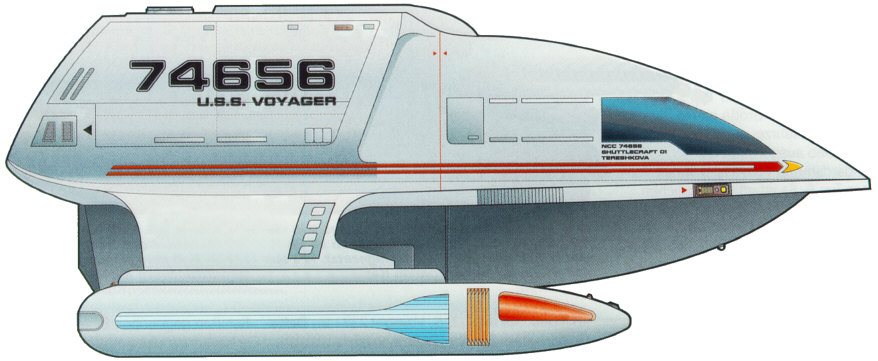
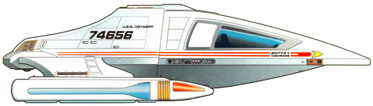
9.2.5 TYPE-7 PERSONNEL SHUTTLE (UPRTD)
Type:
Medium short-range warp shuttle.
Accommodation: Two flight crew, six
passengers.
Power Plant: One 150 cochrane warp engine,
two 750 millicochrane impulse engines, four RCS thrusters.
Dimensions: Length, 8.5 m; beam, 3.6 m;
height 2.7 m.
Mass: 3.96 metric tones.
Performance: Sustained Warp 4.
Armament: Two Type-V phaser emitters.
With the borders of the Federation ever expanding as Starfleet reached the latter half of the 24th Century, the ASDB realized that there was sufficient need for a shuttlecraft capable of making the week-long journeys between planets and stations at low warp. The Type-7 was the first step in this direction, and is equipped for short-range warp travel. To offer comfort to its occupants, the shuttle contains a standard replicator system and sleeping compartments. The forward and aft compartments are separated by a small, informal living area that has a workstation and table. The aft area is normally equipped with a bunk area, but can easily be converted to allow for increased cargo capabilities. A medium-range transporter and atmospheric flight capabilities allow for the Type-7 to service starbases, starships and stations. Ships of this type are currently in use aboard most medium to large sized starship classes, as well as aboard stations and Starbases.
Major technological advancements in the 2370’s allowed for further upgrades to be made to the engine systems aboard shuttlecraft. These upgrades make this craft more capable of long-range spaceflight and, like its starship counterparts, no longer damages subspace.
9.2.6 TYPE-8 PERSONNEL SHUTTLE
Type:
Light long-range warp shuttle.
Accommodation: Two flight crew, six
passengers.
Power Plant: One 150 cochrane warp engine,
two 750 millicochrane impulse engines, four RCS thrusters.
Dimensions: Length, 6.2 m; beam, 4.5 m;
height 2.8 m.
Mass: 3.47 metric tones.
Performance: Warp 4.
Armament: Two Type-V phaser emitters.
Based upon the frame of the Type-6, the Type-8 Shuttlecraft is the most capable follow-up in the realm of personnel shuttles. Only slightly larger, the Type-8 is equipped with a medium-range transporter and has the ability to travel within a planet’s atmosphere. With a large cargo area that can also seat six passengers, the shuttle is a capable transport craft. Slowly replacing its elder parent craft, the Type-8 is now seeing rapid deployment on all medium to large starships, as well as to Starbases and stations throughout the Federation.
9.2.7 TYPE-9 PERSONNEL SHUTTLE
Type:
Medium long-range warp shuttle.
Accommodation: Two flight crew, two
passengers.
Power Plant: One 400 cochrane warp engine,
two 800 millicochrane impulse engines, four RCS thrusters.
Dimensions: Length, 8.5 m; beam, 4.61 m;
height 2.67 m.
Mass: 2.61 metric tones.
Performance: Warp 6.
Armament: Two Type-VI phaser emitters.
The Type-9 Personnel Shuttle is a long-range craft capable of traveling at high warp for extended periods of time due to new advances in variable geometry warp physics. Making its debut just before the launch of the Intrepid-class, this shuttle type is ideal for scouting and recon missions, but is well suited to perform many multi-mission tasks. Equipped with powerful Type-VI phaser emitters, the shuttle is designed to hold its own ground for a longer period of time. Comfortable seating for four and moderate cargo space is still achieved without sacrificing speed and maneuverability. As is standard by the 2360’s, the shuttle is equipped with a medium-range transporter and is capable of traveling through a planet’s atmosphere. With its ability to travel at high-warp speeds, the Type-9 has been equipped with a more pronounced deflector dish that houses a compact long-range sensor that further helps it in its role as a scout. The Type-9 is now being deployed throughout the fleet and is especially aiding deep-space exploratory ships with its impressive abilities.
9.2.8 TYPE-9A CARGO SHUTTLE (UPRTD)
Type:
Heavy long-range warp shuttle.
Accommodation: Two flight crew.
Power Plant: One 150 cochrane warp engine,
two 750 millicochrane impulse engines, six RCS thrusters.
Dimensions: Length, 10.5 m; beam, 4.2 m;
height 3.6 m.
Mass: 8.9 metric tones.
Performance: Warp 4.
Armament: Two Type-V phaser emitters.
Short of a full-fledged transport ship, the Type-9A Cargo Shuttle is the primary shuttle of choice for cargo runs at major Starfleet facilities. Originally developed by the ASDB team stationed at Utopia Planitia, the 9A served as cargo vessel that carried components from the surface of Mars to the facilities in orbit. While able to travel at warp velocities, the 9A is somewhat slow at sub-light speeds, especially when carrying large amounts of cargo. The front of the shuttle is divided by a wall with a closable hatch, allowing for the aft area to be opened to the vacuum of space. The 9A also has the ability to carry one Sphinx Workpod in the aft area. A medium-range transporter and atmospheric flight capabilities allow it to easily complete its tasks. While rarely seen stationed aboard all but the largest starships, the Type-9A is a common site at any large Starfleet facility.
In response to the need to transporter ground troops into areas heavily shielded, a variant designated the Type-9B was designed and is capable of carrying 40 troops and their equipment to the surface of a planet or interior of a space station. This variant has seen limited service onboard frontline ships, most notably the Steamrunner-class starship.
Major technological advancements in the 2370’s allowed for further upgrades to be made to the engine systems aboard shuttlecraft. These upgrades make this craft more capable of long-range spaceflight and, like its starship counterparts, no longer damages subspace.
9.2.10 WORK BEE

Type:
Utility craft.
Accommodation: One operator.
Power Plant: One microfusion reactor, four
RCS thrusters.
Dimensions: Length, 4.11 m; beam, 1.92 m;
height 1.90 m.
Mass: 1.68 metric tones.
Performance: Maximum delta-v, 4,000 m/sec.
Armament: None
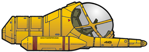
The Work Bee is a capable stand-alone craft used for inspection of spaceborne hardware, repairs, assembly, and other activates requiring remote manipulators. The fully pressurized craft has changed little in design during the past 150 years, although periodic updates to the internal systems are done routinely. Onboard fuel cells and microfusion generators can keep the craft operational for 76.4 hours, and the life-support systems can provide breathable air, drinking water and cooling for the pilot for as long as fifteen hours. If the pilot is wearing a pressure suit or SEWG, the craft allows for the operator to exit while conducting operations. Entrance and exit is provided by the forward window, which lifts vertically to allow the pilot to come and go.
A pair of robotic manipulator arms is folded beneath the main housing, and allows for work to be done through pilot-operated controls. In addition, the Work Bee is capable of handling a cargo attachment that makes it ideal for transferring cargo around large Starbase and spaceborne construction facilities. The cargo attachment features additional microfusion engines for supporting the increased mass.
9.2.11 TYPE-M1 SPHINX WORKPOD
Type:
Light industrial manipulator (Sphinx M1A), medium industrial
manipulator (Sphinx M2A), medium tug (Sphinx MT3D).
Accommodation: Pilot (M1A, M2A); pilot and
cargo specialist (MT3D).
Power Plant: One microfusion reactor, four
alfinium krellide power storage cells, four RCS thrusters.
Dimensions: Length, 6.2 m; beam, 2.6 m;
height 2.5 m.
Mass: 1.2 metric tones.
Performance: Maximum delta-v, 2,000 m/sec.
Armament: None
Along with the Work Bee, the various Sphinx Workpod types are a common site in any large Federation shipbuilding facility. Intended never to be far from its parent facility, the Workpod was designed to allow greater user hands-on control of the various functions involved with day-to-day construction and repair. With more tools then the Work Bee, the Sphinx M1A and M2A are used primarily to manipulate spaceborne hardware during construction. The Sphinx MT3D is a third variant of this robust design, and can be used for towing objects to and from the construction site. Furthermore, a group of MT3D units can work together to tow larger objects into place, including most starship classes, when large tractor emitters are not an option. All three variants utilize the same basic systems, and are small enough to fit inside of a Type-9A Cargo Shuttlecraft. All variants of the Sphinx Workpod are commonly found at Federation Fleet Yards and Starbases, as well as on larger Starfleet vessels.
Missions for a Nebula-Class vessel may include, but are not limited to, the following:
The ability given to the Nebula-class by the changeable pod-module allow the ship to perform almost any mission assigned to it by Starfleet Command.
The normal flight and mission operations of the Nebula-class starship are conducted in accordance with a variety of Starfleet standard operating rules, determined by the current operational state of the starship. These operational states are determined by the Commanding Officer, although in certain specific cases, the Computer can automatically adjust to a higher alert status.
The major operating modes are:
During Cruise Mode, the ship’s operations are run on three 8-hour shifts designated Alpha, Beta, and Gamma. Should a crisis develop, it may revert to a four-shift system of six hours to keep crew fatigue down.
Typical Shift command is as follows:
Though much of a modern starship’s systems are automated, they do require regular maintenance and upgrade. Maintenance is typically the purview of Engineering, but personnel from certain divisions that are familiar with them can also maintain specific systems.
Maintenance of onboard systems is almost constant, and varies in severity. Everything from fixing a stubborn replicator, to realigning the dilithium matrix is handled by technicians and engineers on a regular basis. Not all systems are checked centrally by Main Engineering; to do so would occupy too much computer time by routing every single process to one location. To alleviate that, systems are compartmentalized by deck and location for checking. Department heads are expected to run regular diagnostics of their own equipment and report anomalies to Engineering to be fixed.
Systems
Diagnostics
All key
operating systems and subsystems aboard the ship have
a number of preprogrammed diagnostic software and procedures for use
when actual or potential malfunctions are experienced. These various
diagnostic protocols are generally classified into five different
levels, each offering a different degree of crew verification of
automated tests. Which type of diagnostic is used in a given situation
will generally depend upon the criticality of a situation, and upon the
amount of time available for the test procedures.
Level 1 Diagnostic - This refers to the most comprehensive type of system diagnostic, which is normally conducted on ship's systems. Extensive automated diagnostic routines are performed, but a Level 1 diagnostic requires a team of crew members to physically verify operation of system mechanisms and to system readings, rather than depending on the automated programs, thereby guarding against possible malfunctions in self-testing hardware and software. Level 1 diagnostics on major systems can take several hours, and in many cases, the subject system must be taken off-line for all tests to be performed.
Level 2 Diagnostic - This refers to a comprehensive system diagnostic protocol, which, like a Level 1, involves extensive automated routines, but requires crew verification of fewer operational elements. This yields a somewhat less reliable system analysis, but is a procedure that can be conducted in less than half the time of the more complex tests.
Level 3 Diagnostic - This protocol is similar to Level 1 and 2 diagnostics but involves crew verification of only key mechanics and systems readings. Level 3 diagnostics are intended to be performed in ten minutes or less.
Level 4 Diagnostic - This automated procedure is intended for use whenever trouble is suspected with a given system. This protocol is similar to Level 5, but involves more sophisticated batteries of automated diagnostics. For most systems, Level 4 diagnostics can be performed in less than 30 seconds.
Level 5 Diagnostic - This automated procedure is intended for routine use to verify system performance. Level 5 diagnostics, which usually require less than 2.5 seconds, are typically performed on most systems on at least a daily basis, and are also performed during crisis situations when time and system resources are carefully managed.
11.1 EMERGENCY MEDICAL OPERATIONS
As on most starship classes the Nebula-class has set proceedures in case the vessel encounters a medical emergency which Sickbay cannot handle on it's own. The Holodecks are pre-programmed with holographic medical facilities that can supplement those in Sickbay. At the same time equipment modules stored in the cargo bays and shuttlebays can be set up to act as emergency medical facilities. When longer term care is necessary, quarters onboard can be reconfigured to provide necessary medical support as well as private comfort.
Pods are located on decks below Deck 2. Each pod can support a total of eighty-six person-days (meaning, one person can last eighty-six days, two can last for forty-three, etc.). Two pods are reserved for the top four officers in the chain of command on each vessel, because they are the last four to leave the ship. These are located on Deck three. As the number of experienced Captains dwindles in Starfleet, the notion of a Captain going down with his ship has been abolished. If the ship is abandoned, the top four officers in the chain of command will wait until everyone else is off the ship, opt to arm the auto-Destruct (not always necessary, but there if needed), and then leave in the two escape pods. The current lifepods are called ASRVs, or autonomous survival and recovery vehicles. The first group of these were delivered in 2337 to the last Renaissance Class starship, the USS Hokkaido.
11.3 RESCUE AND EVAC
OPERATIONS
![]()
In situations where more than one atmosphere is necessary it reduces the volume available for consistent density. An example of this is when one hundred persons of an N Class atmosphere must be evacuated along with eight thousand persons of an H Class atmosphere. As neither one can share the M Class atmosphere used aboard most Starfleet vessels, and they cannot share each other's atmosphere, each group must be seperated from the others. This breaks down to the density of the H Class evacuees being much higher than that of the N Class or M Class, and thus also reduces the amount of space available for any other evacuee groups because the N Class is taking up space that it doesn't use but cannot transfer elsewhere.
The transporter is an ideal way to evacuate personnel from dangerous locations. When transporting to the ship the emergency transporters are not available, as these are beam out only. This is the reason for the difference between to and from ship limits. However, in both cases the cargo transporters were utilized in the figures.
Shuttlecraft are also available for rescue and evacuation operations, though operations are limited by the number of qualified pilots. Standard procedures call for four short-range shuttlecraft to be fully operational at all times, two able to launch within 5 minutes’ notice, with the third and fourth able to launch within 30 minutes. Procedures also call for at least three medium or long-range shuttles to be fully operational at all times, with one on hot stand-by, able to launch within 5 minutes. The remaining operational shuttles can be launched within 30 minutes.
Evacuation figures for shuttlecraft are difficult to estimate, since the number can vary depending on various factors, including: distance between the ship and the target location, available shuttles, top capacity for the shuttles and number of qualified pilots and technicians.
Further information on Rescue and Evac Operations can be found in any Starfleet Database.
APPENDIX A -
AVAILABLE POD MODULES
![]()
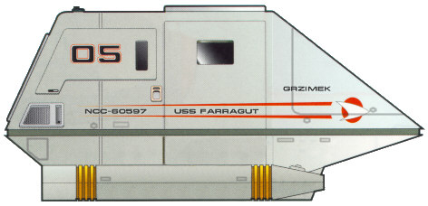
The Nebula-class is unique in that it has a large interchangeable equipment module located at the rear of the ship. The ‘pod’ as it is sometimes called, can be replaced with another - sometimes within a few days - when performed at a starbase. Changing pods is a very involved process, and frequent module changes can cause undue stress on the ship. As such, procedure dictates that the ship must not change modules more often than every 6 months without due reason. Such reasons could include damage to the previous module, special missions from Starfleet, or testing new equipment.
The original Nebula-class vessels utilized an elliptical module, which was connected to the engineering section by two reinforced struts. Revisions to the structure later changed the connecting pylon to a singular connection strut. This revision also included a new module design, in the form of a triangular module. This design officially replaced the elliptical module in 2370, and ships are being upgraded as time and resources allow. Completion of the upgrade is expected fleet-wide by 2380.
There are several different pods available, some of which are outlined below.
Sensor pod: The majority of the first Nebula-class ships were outfitted with this pod, which greatly extended the ship’s sensor range. With this pod the Nebula-class ship is virtually unmatched in regards to sensor capability. Ships with this pod module were routinely assigned to deep-space exploration, hostile border patrols or long-range reconnaissance.
Weapons pod: With the recent Borg invasions and Dominion War, Starfleet quickly mobilized to deploy the weapons pod, which contains 8 forward-facing torpedo launchers, and 3 Type X point-defense phaser emitters. The launchers are fed by an additional 200 photon torpedoes stored in the pod itself. While equipped with eight launchers, each launcher is a smaller type similar to that used by Intrepid-class ships, and as such can only fire up to 3 torpedoes at once, with a reload time of 6 seconds. Later versions of the pod are also equipped with a limited number of quantum torpedoes. The weapons pod is also equipped with two shield generators (one main, one backup), since it was realized that the pod would be an easy target. The shield generators are the same type used through-out the rest of the ship, and draw power directly from the auxiliary energy reserves during Red Alert situations.
Tactical pod: This is a recent addition to the Nebula-class fleet, and is quickly becoming the default module for all new Nebulas being built. The design combines the scanning capabilities of the sensor pod and the offensive capabilities of the weapons pod into one module. There are disadvantages to this design. The tactical pod contains 75 less torpedoes (125), in order to make room for the sensor pallets. Also, the scanners are primarily designed to aid in targeting for the torpedoes and phasers, and as such are not optimized for long-range usage.
Hospital pod: This specialty pod, while not found in wide-spread use, includes the same medical facilities found in large starbases and is equipped to handle several hundred casualties at once.
Habitation/Colony pod: This pod contains a large number of residential quarters, and is sometimes used on long-term missions, or on missions focusing on populating a colony. Depending on configuration, up to 6,000 people can be ferried in the habitation module. With slight modifications, this module can be configured to act as a troop transport, enabling the ship to carry several thousand troops. During the offensive on Cardassia Prime at the end of the Dominion War, several habitation pod-equipped ships were used with great efficacy to transport Marines to the front lines. This module also contains a dozen dedicated transporters, allowing the roughly 5,000 troops to be beamed out within a relatively short amount of time.
Shuttlebay/Hangar pod: This experimental pod includes a large shuttle hangar with the space to hold over two dozen runabouts and fighters. Further information regarding maximum capacity and capabilities is classified pending review by Starfleet Command.
Skid pod: This pod, while rarely used, can be used to tow a smaller ship at high warp for extended distances. The pod consists of two elongated pylons, which are then connected to another ship with reinforced bolts. By not using tractor beams, the Nebula-class ship is able to divert more power to the structural integrity field, and thus travel at a higher velocity for a longer period of time.
Miniature Warp Nacelles: This type of pod is still considered experimental, and most likely will not be approved for fleet-wide use. The design features two nacelles, each approximately one-third scale, positioned directly above the main nacelles. While not giving the ship a higher warp speed, it does allow the ship to maintain high warp for a longer period of time. Given the amount of work that must be put into properly connecting the mini-nacelles, they are likely to remain in the experimental phase for some time. At this time, only four Nebula-class starships are equipped with this “module”.
Most Nebula-class ships are assigned two main modules (one sensor and one weapons module), though some ships are also given a specialty module (hospital/habitation/skid). Some ships are making the tactical pod their main module, since it combines the abilities of the two main pods. At this time, the Hangar Pod is found on only a select number of ships. In order to exchange pods, the ship must be docked at a certified facility for a minimum of two days, to give suitable time to perform diagnostics on all connections and systems. The exchange must be approved by both the ship’s captain and the station commander. An upgrade recently approved by Starfleet Command allows a Nebula-class ship to have ablative armor installed over critical points on the ship, mostly centered on the points connecting the pod-module to the ship itself. This upgrade is currently limited to ships serving on the out-skirts of the Federation border, or near hostile borders, due to limited resources.
Many of the above modules contain habitable decks, and are referred to by letters; Deck A would be the top-most deck, deck B would be below it, and so on. Access to these decks is normally restricted, due to the sensitivity of the surrounding areas.
APPENDIX
B - BASIC TECHNICAL SPECIFICATIONS ![]()
ACCOMMODATION
Officers and
Crew: 750
Visiting Personnel: 130
Evacuation Limit: 9,800
DIMENSIONS
Overall
Length: 442.23 meters
Overall Height: 130.43 meters
Overall Beam: 318.11 meters
PERFORMANCE
Maximum Velocity Warp: Warp 9.2 (Max Cruise Speed), Warp 9.6 (STD 12 Hours Max), Warp 9.9 (UPRTD 12 Hours Max)
ARMAMENT
Standard - 8
Type X phasers, 2 torpedo launchers
With Weapons Pod - 11 Type X phasers, 8 torpedo launchers
(200 additional torpedoes)
TRANSPORT EQUIPMENT
Shuttlecraft
Transporters
APPENDIX
C - VARIANT
DESIGNATIONS ![]()
The following section describes current variants for the Nebula Class vessel. Because of the versatility offered by the interchangeable module, Starfleet has chosen not to fund research into variants at this time. It could however be argued that by utilizing a different module, the ship is infact already a variant.
STANDARD (STD): This was the the Nebula Class as it originally launched in the 2350s.
UPRATED (UPRTD): This is the current version of the class, and contains a warp core upgrade as well as various hardware upgrades. For further information on this upgrade, refer to the technical specifications for the Galaxy Class.
Deck 1 - Captain's
Ready Room, Main Bridge, Observation Lounge
Deck 2 - Junior Officer's Quarters, Environmental
System Controls
Deck 3 - Junior Officer's Quarters, Upper
Shuttlebay, Shuttlebay Upper Maintenance Bay
Deck 4 - Main
Shuttlebay, Main Shuttlebay Maintenance Bay, Shuttlebay Operations
Deck 5 - Shuttlebay
Lower Maintenance Bay, VIP Accommodations
Deck 6 - Transporter Room 1-4, Main Science Labs
Deck 7 - Senior Officer’s Quarters,
Arboretum
Deck 8 - Crew
Quarters, Commanding Officer Quarters, Executive Officer Quarters, VIP
Quarters
Deck 9 - Senior
Officer’s Quarters, Stellar Cartography (Main Entrance)
Deck 10 - Ten-Forward Lounge, Stellar Cartography
(Lower Bay), Holodecks (Upper Bay)
Deck 11 - Holodecks 1-4 (Main Entrance), Holosuites,
Gymnasium 1-2 (High Bay), Banquet Halls
Deck 12 - Main Sickbay, Sickbay Main Computer,
Surgical Ward, Neo-natal Ward, Biohazard Ward, Critical Triage Ward,
Primary ICU, Overflow ICU, Trauma Stasis Unit, Medical Sciences Ward
Deck 13 - Cargo Bays 1-2, Residential Quarters
Deck 14 - Cargo Bay 3-4, Residential Quarters
Deck 15 - Cargo Loading Doors, Armory
Deck 16 - Captain's Yacht Docking Port
Deck 17 – Crew Quarters
Deck 18 - Crew Quarters
Deck 19 – Crew Quarters
Deck 20 - Crew Quarters
Deck 21 - Holosuites
Deck 22 - Structural Integrity Field Systems, Matter
Injectors
Deck 23 - Deflector Dish
Deck 24 – Main Engineering, Sensor
Maintenance
Deck 25 - Science Labs
Deck 26 - Aft Torpedo Launcher, Defensive Shield
Systems
Deck 27 - Environmental Support, Waste Management
Deck 28 - Cargo Bays
Deck 29 - Antimatter Supply Manifold, Antimatter
Storage Pods
Deck 30 - Tractor Beam Emitter, Antimatter
Generator, Antimatter Injector, Antimatter Loading Hatch, Warp Engine
Core Jettison Hatch
FROM THE DESK OF MIKE STANNARD:
When I first saw the Nebula-class starship (‘NCS’ from here on) in a few TNG episodes, I saw it for what it appeared to be – a cheaper version of the Galaxy-class. And indeed it is, but it’s more than that. With the adaptability given to it by use of the swappable pod-module, the Nebula-class is one of the most versatile starships ever seen in Star Trek. While some of the pods (Shuttlebay, Hospital) may not be considered canon, it should be noted that the sensor and weapons modules have not been specifically mentioned by name either. In the early TNG episodes, an elliptical dome was featured on the NCS, yet later it was a triangular pod. Different modules all-together, or simply an upgraded design? Until we learn from canon sources otherwise, I’m going to make the assumption that the elliptical dome was/is the older, original module, and the triangular pod is the newest module.
One of the greatest things of the NCS is that they can be used for almost any possible mission. Diplomatic relations, defense, exploration, testing new technologies… That gives the Ship Manager (and crew) of Nebulas virtually limitless possibilities while it comes to missions. Also, because the design of the ship so closely resembles that of the Galaxy-class, much of the major systems are identical, which allows the crew to more easily visualize different parts of the ship.
I bring up the similarities with the Galaxy-class ship because much of the information contained in the NCS specifications was adapted from The Next Generation Technical Manual. Truth be told, I had it easier than most of the others involved in the Technical Specifications Committee. The other members should really be commended for their work, as most of them had A LOT less canon information to go on than I did. They did a fantastic job of filling in the gaps, and I applaud them for an accomplishment they should all be proud of.
Bridge Layout: “You’re using the same layout as the Galaxy-class?? But didn’t the Nebula-class USS Sutherland that Data commanded use a much smaller Bridge??” Response – Yes, but we must remember that the Bridge is an easily ejectable/changeable module, and as such the Bridge could conceivably be configured and customized depending on available crew and anticipated missions. “Okay then.. so my ship doesn’t NEED to use the Galaxy-class module..” Response – No, it doesn’t. The SM is free to use a custom bridge if they so desire. In fact, the Bridge shown in Star Trek: Generations includes two additional stations on the port and starboard side of Conn and Ops, which were not seen in (most) episodes of The Next Generation.
Number of Decks: “30 decks?? ST:ACTD specs have always said 38!” Response – If you place a side view of a Nebula-class on top of a Galaxy-class, the Nebula will show to be missing about 12 decks. Galaxy has 42 decks, so 42 minus 12 equals 30.
Ten-Forward Lounge: “Ten-Forward is the Lounge on the Enterprise-D, why do you call it Ten-Forward on a Nebula-class?” Response – Ten-Forward refers to the location: Deck 10, forward section. Therefore, it made sense to keep that designation. Individual ships are of course welcome to name their lounges.
Main Engineering: “How did you come up with Deck 24 as the location for Main Engineering??” Response – On a Galaxy-class (42 decks), Main Engineering is located on deck 36, 6 decks above the bottom.. 30 decks (see note above) minus 6 equals 24.. Seems logical, right?
Bio-Neural Gel Packs: Nope, not on the Nebula. Why? There’s no reason to have them. They are on the newer ships (Intrepid, Sovereign), and as such are not on the older ships. It’s my belief that in order to upgrade a ship to use BNGP, a lot of the main infrastructure would have to be pulled out and re-arranged. Too much work.
- Mike Stannard - February 11, 2002 (10202.11)
APPENDIX
F - CREDITS AND COPYRIGHT INFORMATION ![]()
NEBULA-CLASS SPECIFICATIONS CREATED BY:
Primary research and design by: MIKE STANNARD
Additional research by: Sam Hung
Original deck layout conceived by: David Foley
Additional thanks go to: MikeJ, ChrisN, GregV, MarkT, DaveS
SOURCES USED:
Copyright 2001 - Star Trek : A Call to Duty. Use of these specifications is restricted to the Star Trek: A Call to Duty (ST:ACTD) Technical Specifications domain at http://techspecs.acalltoduty.com and may only be reproduced with the express permission of the ST:ACTD on sites that clearly serve to provide information on ST:ACTD, its various ships and stations, or other related topics. Editing the contents of the information present on this page or reformatting the way in which it is presented is not permitted without the direct permission of ST:ACTD. Wherever possible, published sources were consulted to add to the wealth of knowledge in this document, and in some cases, this text was reproduced here. Sources used are properly cited in the "Credits and Copyright Information" appendix. No copyright infringement is intended.