
Buckingham-Class Starbase
UNITED FEDERATION OF PLANETS: STARFLEET DIVISION
Advanced Technical Specifications for the Buckingham-Class Production Emplacement
|
Accommodation: ~20,000 stationed personnel, 2,500-5,000 visiting personnel, varying civilian population Classification: Support Station [Support/Economic/Defensive/Diplomatic] Funding for Buckingham Class Development Project Provided by: Starfleet, Daystrom Institute of Technology, Jupiter Station Research Facility, Advanced Starship Design Bureau, Federation Council Development Project Started: 2271 Production Start Date: 2271 Prototype Commissioned: 2288 Production End Date: Still in Production Current Status: In Service |
Locations of Major Buckingham-Class Manufacturing Facilities: Earth Station McKinley, Earth; San Francisco Fleet Yards, Earth; Utopia Planitia Fleet Yards, Mars; Venus Construction Yards, Venus; Baikonur Cosmodrome, Earth; Newport News Fleet Yards, Earth; Cosmadyne Yards, Boston; Pederson Spaceport, Copenhagen; Port Copernicus Fleet Yards, Luna; Chandley Works, Caravalia; Axaanivus Cesleco Starcraft, Bedii Plains, Alpha Centauri V; Tellar Fleet Yards; Seskon Trella, Chagala; Andor Fleet Yards; Chiokis Starship Construction, Thelavor; 40 Eridani A Fleet Yards; Shor Ta'kel, Central Docks, 40 Eridani; New Aberdeen Fleet Yards; Antares Fleet Yards, Antares IV; Beta Antares Yards, Antares IV; Avondale Group, Ferrata Docks, Rigellium, Rigel II; Alfras Fleet Yards, Deneb V; M'Yengh Yards, Shzerensohr, Cait; Betazed Fleet Yards, Starbase G-6; Trill Fleet Yards, Trill; Starbase 12 Current Starship Identification and Registration Numbers:
|
1.0
BUCKINGHAM-CLASS INTRODUCTION ![]()
Pursuant to Starfleet Directives 905.5 & 910.3, Starfleet Defense Directives 138.6, 141.1 & 154.7, and Federation Security Council General Policy, the following objectives have been established for the Buckingham class station:
Length: not available [this
measurement is dependent upon the modules connected]
Width: 1142 meters
Height: 1713 meters
Weight: 80,220,400 metric kilotons [main hull only]
Hull: Duranium microfoam and
tritanium plating
Number of
Levels: 82.
The Buckingham class station is the Federation's largest production station, and only second to the Taj Mahal Class in size [the Taj Mahal never went into full production]. Their purpose is to support Federation, Starfleet, and allied vessels within the area. This support ranges from refueling and resupply to refit in some cases. These stations also serve a vital economic purpose, with their onboard manufacturing systems. At the same time, the stations can also stand in as a seat of government providing control for commerce in the area. As with all Starfleet installations, Buckingham class stations serve a vital defensive & diplomatic purpose as well. Such a large facility can perform support tasks that can keep an entire fleet of starships working against a threat force. At the same time, the actual presence of a Federation installation of this scale within reach of many diplomatic attachés make these stations important centers for diplomatic exchange.
Long before the mid 24th century, when these stations came into their full use, Starfleet saw the future need. When Spacedock 1 was designed in the 2260's, Starfleet realized the great potential of having orbital stations throughout the Federation. But when planners calculated the entire project's cost, the numbers were too much for anyone to sign off on. It was decided to use another design for the station. In 2271, when the splinter Buckingham Class projected began Starfleet called for a review of all designs that were submitted for Spacedock 1. Many designs within the group met the requirements Starfleet had set, but this didn't satisfy Starfleet. Starfleet included modular adaptations just as the process was ready to be completed near mid March. Fortunately Starfleet narrowed the canidates down to three designs at this time which were easily modified into modular stations.
Before June of 2271 rolled around the design had been approved, jobs divided among contractors, plans drawn up for manufacturing facilities, and construction start on those facilities. Due to Starfleet bookkeeping policies it was decided to mark the construction of the manufacturing facilities as the beginning of production for the Buckingham Class, even though the first set of modules was not completed until 2283, and that was just for the prototype. Another main hull was not completed until two years later. However once the manufacturing facilities were completed, full production was possible. Starfleet ordered that production slow while the prototype was being docked together.
It took nearly fifteen years to complete the prototype, which was manufactured at over thirty different facilities into pre-fabricated components. Most of these parts were assembled into various modules at those facilities. These modules were transported to Sector 029 by Ptolemy Class tugs, where they were docked in 2284. There were only a few small problems noticed in the prototype, those of concern were the docking latches on the lower disk modules. These latches were unable to handle the stress that the schematics had originally predicted. This was most likely due to the fact that a different manufacturer built each module. The solution that Starfleet adopted was to reduce the amount of modules each station could have. The stresses created by the station maneuvering were solved. Other problems were reworked in similar fashion, including the addition of more utility generators [such as power, structural integrity field, inertial dampening field, and gravity generators] to the docking bay. These changes were all included in the first production station that was assembled in 2285 within 1000 meters of a a K series station which was to be decommissioned (interestingly enough this particular K-series station was not immediately decommissioned when it's neighboring Buckingham Class became fully operational. As was the case until about 2330, both stations continued working side by side, but the last case of this symbiosis ended in much ceremony in 2330).
Starfleet was satisfied with the results of the changes and ordered nearly two hundred stations to be built across the Federation. The large percentage was placed well within Federation boarders, but some were built out slightly further. These were not deep space stations, but were far enough out to become major stepping-stones in exploration into deep space outside of Federation territory.
General Overview: Primary operational control for the Buckingham Class station is provided by Operations located on Level 8. Operations directly supervises all primary mission operations and coordinates all departmental activities.
Layout: The current standard Buckingham Class layout is as follows. In the center is the Command area with a circular station. Located here is seating for the command staff when they are present in Operations. This large station provides those at it with access to status and other station information. There is also an auxiliary internal communications control here.
The operations center is a large dome in most cases, and thus has a layout that sometimes negates the terminology of forward and rear. But the front part of operations is considered to be where the main viewer is located, and in the rear is the exit for the Captain's Ready room.
In the front area below the main viewer is a group of stations. The chief positions here are for the Station's Flight Control officer and the Chief of Operations. Some other stations surrounding them include Sector Control [a station that monitors those ships within a twenty light-year radius], Space Dock Control [a station that closely monitors each ship within the docking bay and their current status], and Primary Station Status Control. Primary Station Status Control is a large transparent schematic between these stations and the command area. It is low enough to allow an unobstructed view between the command area and the main viewer. Its purpose is to quickly display the station's status, much like a master systems display screen would on starship bridges. There are control panels at the bottom of this large screen.
To the left of the command area is Tactical and Security. These two stations have control over two areas separately and one area jointly. The docking bay is the area of joint responsibility. Both stations have the responsibility to protect the station and those ships in the docking bay at all times. Security has the same responsibility to protect the station from internal threats, while tactical is oversees those threats that are external. Included with these stations is a read out on all reported civilian issues.
To the right of the command areas is the engineering and science station. The Engineering station uses many of the auxiliary stations next to the Operations station, such as Space Dock Control, to check up on the ships in the docking bay being repaired, refueled, or resupplied by the station's Engineering department. Between the engineering station and the science station is Environmental Control and Library Computer access [a dedicated station specifically used for research of the station's library files]. The Science station is on the other side of these two auxiliary stations from the engineering station.
Other stations scattered throughout Operations are Communications Control, Cargo Control, and Shuttle Control. There are five turbolifts leading out of Operations; one is an emergency turbolift that leads directly to the secondary command center, two lead to separate areas of the docking bay, and two others lead to areas around the rest of the station. The Conference Room and Bridge Head egress is near the Captain's Ready Room at the back of Operations.
While there is a seating station for each member of the Senior Staff, most of them do not take up regular posts here. The CEO and CMO for example will remain in Engineering and Sickbay respectively. The CNS will also be less likely to visit this area of the station as their responsibility leads them elsewhere, especially in the area of Civilian-Crew Communications. The CSO also is kept busy with duties outside of Operations; these usually revolve around the direct supervision of scientific experiments on board as well as review of scientific reports from teams aboard Starfleet vessels across the Federation. For the most part, the CO is also busy within his office. The other members of the Senior Staff usually work from this location of the station.
General Overview: Main Engineering is located on Level 2 of the Buckingham Class. Its primary purpose is to be the central point for control of all engineering systems, especially those relating to power generation. Here is located the Matter Antimatter Reaction Chamber also known as the Power Core. The fact the station is so large has led to the necessity of each primary and secondary system having a dedicated console for monitoring and control. These systems are so important, and so large, that monitoring them becomes ever more important over repairing them. These consoles are grouped together by specific criteria. Most of the secondary systems are on the walls, while the primary systems have table-monitoring stations. The categories that are usually grouped together are Power Generation, Environmental, Tactical, Ship Support, and Repair & Maintenance. Main Engineering is also the location of the Chief Engineer's office.
The Power Core is a horizontal shaft that takes up almost two full Levels in diameter and its length almost reaches from hull to hull between the injectors. Deuterium and antimatter tanks within the lower part of the docking bay feed the core. When the reactants reach the core's reaction chamber they'll react and power will be sent through the power transfer conduits and the Electroplasma system. The power transfer conduits carry the load first; this allows greater efficiency over the long distances it must travel through the station. This also allows for a greater amount of ships to be powered directly by the station's main core.
During emergencies Main Engineering can be turned into a command and control center by converting a number of consoles to duplicate the stations in Operations. The software is already preloaded onto these consoles and each station has specific procedures in place in case a situation warrants.
Spacedock is located at the very top of the station. It is among the station's primary responsibilities. Ships enter the bay by two opposing doorways. Spacedock is separated into multiple areas known as Tiers. The highest point, just below the Subspace Antenna and Long Range Sensor Array, is called Spacedock Engineering. This is where all the support systems for the docked vessels are located.
Extending down inside the bay is a pillar from this point until the bottom. Almost everything is located in this pillar. Just below the Spacedock Engineering area is the Capital Ship Docks, these are specifically designed to service Starfleet vessels, allied fleet vessels, and any diplomatic vessels that visit the station. The next location is the control area for the bay, the Spacedock Control room and the Spacedock Computer Core. The reason the computer core is located here is because it's necessary for it to be isolated from certain devices in the Spacedock Engineering area, it is much more plausible to do this here. The Spacedock Control room is located here out of simple convince.
The next location on down is the entrance for Spacedock, the huge Bay Doors that are located on the outer walls. Electrofluidic pistons operate these massive doors. Also located around the edge of the outer wall is a group of platforms. These platforms take up space that isn't needed for maneuvering by the many starships that enter the bay. They are used to store several thousand metric tons of cargo and supplies. This is also a convenient location for freighter docking on the central pillar. During times of low traffic, the freighters will dock and their cargo will be shuttled over to the platforms. During times of high traffic (and when there is still room within the bay) the freighters will not dock. Instead they will keep position near the cargo platforms and the shuttles will not have to travel across the paths of other incoming and outgoing vessels. Within the pillar here is even more Cargo Storage, usually meant for those items which will be dispersed on the station itself. The next tiers contain areas for passenger and transport docking. This is also the location for temporary layovers. Located within the pillar are temporary residential areas (residency for no more than two weeks), commercial areas, and even a fair amount of recreational activities. Below this is the bottom of the pillar which widens slightly to include more internal space.
Here on the floor of Spacedock is a large amount of flat space. This has been used as Shuttlebay 1 and storage since the beginning of the Buckingham Class, and recently it hasn't been unheard of for ships capable of hard landings to be here. Within the pillar are more cargo and storage areas, usually dedicated to the modular nature of starships and shuttle operations. Outside of that is a large parking lot of Shuttlecraft and Anti-grav platforms, more than any ship could hold. Further out from that, between the shuttle landing pads and the exterior wall is storage for starship modules. Not to be confused with the large station modules, starship modules range from sensor pallets to internal habitat compartments or even the Multi-Mission Modules of the Nebula Class [which must be towed out to be equipped on the Nebula Class]. The modules are arranged by class and module type. This area has no artificial gravity generators, in fact the only force keeping the modules to the floor of the bay are large electromagnetic clips which connect modules to each other in stacks and then to the floor. Most stations carry an assortment of modules for each class especially when they can be interchanged with other classes (the internal compartments of the Nebula and Galaxy Class for instance).
While outside it appears that the bay continues to a narrow point ending just above the command section of the station, this is not true. Just below the floor of the bay are the manufacturing areas for the Buckingham Class station, these are located between Spacedock and the command section. Located here are large replicators including at least one class-4 CFI industrial replicator.
Secondary Spacedock is located on one of the large modules near the bottom of the station. This bay has a large door reminiscent of the K series' station. The door slides open along the interior wall by large electrofluidic pistons. Opposite the door is a series of stacked docking berths that can accommodate most civilian transport liners. These berths are meant for simple embarking and disembarking, long term docking is done in the main bay. They also allow direct transport to the typically civilian areas of the station. A small shuttle bus service is run from this bay to the main bay and back at regular intervals.
Spacedock is the largest portion of the Buckingham Class station's responsibilities. To adequately control this not only is Operation's involved but so is a separate section of the station's command chain. Spacedock Control is located in the central area of the docking tower. From this location ships are remotely piloted once they enter the docking bay. The gangway and utility umbilicals are controlled from here. Cargo loading and unloading must be authorized through this room. Any refueling, resupplying, and repair work is first reported here and then passed on to other departments of the station.
This location is a large circular area that rings the docking tower. There are piloting stations as well as communications, engineering, and operational stations as well. Each ship will be assigned to a set of these stations and will use them to communicate to station command staff. Spacedock Control is also one of the best places to view the docked ships because of the windows looking out over the docking bay.
Starfleet saw it necessary to separate the different generators that the station and the ships use. Access to this area is achieved by heading towards the top of the docking tower, but unlike Main Engineering, this is only a mechanical area. There are only seven generators necessary, power generation [fusion based], gravity, water & waste recycling, replicator service, atmospheric service, structural integrity field, and inertia dampening field. There are no exterior docking ports so shield generators are not necessary for ship support, however there are some shield generators in this area for station use [Addendum: After the advent of large dimension vessels such as the Ambassador, Galaxy, Nebula, and Sovereign, Starfleet did see the need for external docking. External docking is achieved from the modules where a docking gangway will extend out to mate with the ship. Support generators are located nearby within the Modules and because these docks are exterior they do have shield generators]. Deuterium is fed up the docking tower to the fusion reactors in this area. All the services lead to a centralized hub near the center of the docking tower where they then go down a conduit and branch off in umbilical bundles to be connected to the ships. The umbilical bundles can reach a maximum of ninety meters from the docking gangway. After that extensions must be used. The extensions are connected with the help of manipulators attached to Workbees.
2.7
SUBSPACE COMMUNICATIONS NETWORK ![]()
Buckingham Class stations are major stepping-stones in the Subspace Comm Network receiving transmissions from across a 22 light-year radius and passing them on to the next step towards their destination. For centuries a postal service has been a requirement for a true civilization, and the Federation is no different. The Subspace Communication Network provides boosting and amplification for long-range messages. This is all necessary because of physical limitations on all subspace messages. The Subspace Communications Network Hub on Buckingham Class stations receives messages from the large antenna array on the top of the station. From here most messages are quickly processed and sent on, however a staff of 100-200 dedicated personnel work the equipment and help to move along undeliverable messages. Station communications also travel through the antenna array, but not through the Network Hub. SEE: 6.4 COMMUNICATIONS
2.8
STATION MANUFACTURING FACILITIES ![]()
Because stations are called to service and repair those vessels that dock, it is a necessity to have manufacturing facilities for those items that cannot be replicated to acceptable specifications. Most of these facilities are located near the bottom of Spacedock. To this end, all Buckingham Class stations contain Engineering Labs and Manufacturing facilities. For jobs that can be replicated but require large industrial replicators, most Buckingham Class stations have been equipped with at least two Class-4 CFI industrial replicators
Phaser Arrangement:
Primary Hull: Twenty-four Type-11 Main Phaser Turrets spread out in three rows of eight. Sixteen Type-8 Point Defense Phaser Turrets.
Ventral Hull: Four Type-11 Main Phaser Turrets placed at ninety degree in travels. Eight Type-9 Point Defense Phaser Turrets.
Modules: Most modules come equipped with a variety of phaser types on their dorsal and ventral surfaces, but there aren't more than six turrets on each module. All these turrets are for point defense, and so far no modules have been manufactured with anything stronger than Type-9. Some modules have no phasers at all; these are usually placed near the center, instead of further out.
Phaser Output: Each phaser array takes its energy directly from the Power Core and auxiliary fusion generators. Each type of phaser denotes a different maximum power level. The Type-8 phasers achieve an output of about 4.1 megawatts, Type-9 achieves 4.5 megawatts, and the Type-11 achieves an amazing 6.1 megawatts.
Phaser Array Range: Maximum effective range is 300,000 kilometers.
Primary purpose: Assault
Secondary purpose: Defense/anti-spacecraft/anti-fighter
Arrangement: There are only six torpedo launchers designed into the Buckingham Class station. The first four are placed in between the docking bay doors. They service threat vessels coming from all axes but negative z, which is blocked by the modules. The remaining two launchers are in the ventral hull at ninety-degree angles from the docking latches for the modules. These launchers have a more limited firing arc because the modules block them.
As a station, the Buckingham class has the materials in storage and the equipment on board to manufacture more torpedo casings than it currently carries in ready stock.
Type: Mark XXV photon torpedo, capable of pattern firing (sierra, etc.) as well as independent launch. Independent targeting once launched from the station, detonation on contact unless otherwise directed.
Payload: Buckingham Class stations store an average of 500-photon torpedo packages dedicated for station use outside of emergencies [in emergencies part of the station's torpedo compliment can be siphoned to allied vessels]. Only a few stations carry a supply of quantum torpedoes, those nearest hostile territory come first. More torpedo packages are stored for resupply purposes.
Range: Maximum effective range is 3,000,000 kilometers.
Primary purpose: Assault
Secondary purpose: Anti-spacecraft
Type: Symmetrical subspace graviton field. This type of shield is fairly similar to those of most Starships. Under Starfleet Directives all facilities incorporate the nutation shift in frequency. During combat, the shield sends data on what type of weapon is being used on it, and what frequency and phase the weapon uses. Once the tactical officer analyzes this, the shield can be configured to have the same frequency as the incoming weapon - but different nutation. This tactic dramatically increases shield efficiency.
Output: There are a total of forty-eighty shield generators on the Buckingham Class. Each generator has a cluster of twelve thirty-two megawatt graviton polarity sources feeding a pair of six hundred twenty five millicochrane subspace field distortion amplifiers. During emergency situations the generators are synchronized together providing two thousand six hundred eighty-eight megawatts continuously. The maximum peak load is four hundred seventy-three thousand megawatts for one hundred seventy milliseconds.
Range: The shields, when raised, operate at two distances. One is a uniform distance from the hull, averaging about ten to twelve meters. The other is an elliptical bubble field, which varies in distance from any single point on the hull but has a common center within the station.
Primary purpose: Defense from enemy threat forces, hazardous radiation and micrometeoroid particles.
Number of computer cores: five primary cores. Because stations are so large, designers decided that it would be more efficient to have a larger amount of cores, than to have long utility lines. The largest core is in the command section, which functions mainly for station operations only. The second largest core is the spacedock core, which is near the center of the docking bay. This computer controls all those ships docked, those ships entering or leaving the docking bay, and it also provides the largest area of storage for Starfleet records. This second core is in fact the only one equipped with it's own subspace transceiver assembly. Two other cores provide computer power for the station's secondary missions and population. The remaining primary core acts as a back up, while it is used as a secondary core, it's equipment and setup is that of a primary core.
Type: The computer cores on Buckingham Class stations are isolinear storage devices utilizing faster than light processing drives with isolinear temporary storage.
Acronym for Library Computer Access and Retrieval System, LCARS is the common user interface of 24th century computer systems, based on verbal and graphically enhanced keyboard/display input and output. The graphical interface adapts to the task that is supposed to be performed, allowing for maximum ease-of-use. The Buckingham Class operates on LCARS build version 5.2 to account for increases in processor speed and power, and limitations discovered in the field in earlier versions, and increased security. The operating version receives minor upgrades any time they are available when contact with another Starfleet vessel or facility is made. Stations also receive major upgrades every six months, which include an updated version of the combined Federation and Starfleet Database.
Access to all Starfleet data is highly regulated. A standard set of access levels have been programmed into the computer cores of all Starfleet installations in order to stop any undesired access to confidential data.
Security levels are also variable, and task-specific. Certain areas of the station are restricted to unauthorized personnel, regardless of security level. Security levels can also be raised, lowered, or revoked by Command personnel.
Security levels in use aboard the Buckingham Class are:
Level 10 – Captain and Above
Level 9 – First Officer
Level 8 - Commander
Level 7 – Lt. Commander
Level 6 – Lieutenant
Level 5 – Lt. Junior Grade
Level 4 - Ensign
Level 3 – Non-Commissioned Crew
Level 2 – Civilian Personnel
Level 1 – Open Access (Read Only)
Note: Security Levels beyond current rank can and are bestowed where, when and to whom they are necessary.
The main computer grants access based on a battery of checks to the individual user, including face and voice recognition in conjunction with a vocal code as an added level of security.
All Starfleet installations make use of a computer program called a Universal Translator that is employed for communication among persons who speak different languages. It performs a pattern analysis of an unknown language based on a variety of criteria to create a translation matrix. The translator is built in the Starfleet badge and small receivers are implanted in the ear canal. The station's computer is also quite good at adapting to alien translation devices and utilizing them during conferences.
The Universal Translator matrix aboard Buckingham Class stations consists of well over 100,000 languages and increases with every new encounter.
Type:
NNEC Mark 4.5 Standard Matter/Anti-Matter Reaction Drive, developed by
Newport News Engineering Consortium adapted for station purposes.
Normal Power Output: 105
megawatts
Standard Peak Output: 107
megawatts
Maximum Power Output: 109
megawatts
The Main Reactor Core for the Buckingham Class station was originally designed for the Excelsior Class. Before the stations were completed the Excelsior Class was in flight trials for the Transwarp Propulsion system, which more than proved the viability of its power plant. Designers decided to scrap the original idea to adapt the refit Constitution Class' power plant. This decision eventually saved Starfleet from an extensive refit process in the future because of the hardened nature of that power plant.
Type: Standard Galaxy Class Impulse drives developed and built by Theoretical Propulsion Group in conjunction with the Advanced Starship Design Bureau - Utopia Planitia Division.
Output: 108 to 1011 megawatts per module pack [6 generators to a single pack].
The Buckingham Class was refit with new fusion cores during the 2340's and 2350's. During the operational lifetimes of the stations they had received newly built cores based on the original specs at least three times, some stations received five such upgrades. But after half a century of service, Starfleet saw the need for more power. For the most part the replacement of the Fusion Cores was a simple matter. Take out the original cores and the isolation track system they were attached to. Install a new track and then put in the new cores. However, in some cases [especially in the Spacedock Engineering area], modifications to the EPS system were necessary. These modifications continue to prove advantageous over the older specs.
Type: Standard magnetohydrodynamic gas-fusion thrusters designed specifically for the Buckingham Class.
Output: Each thruster quad can produce 8 million newtons of exhaust.
Tractor Emitter: All Reaction Control System Thruster packages on the Buckingham Class have small tractor beam emitters. These emitters help provide more coverage for the station entire tractor beam system.
6.0
UTILITIES AND AUXILIARY SYSTEMS ![]()
A standard Buckingham Class deflector grid is located all along the hull of the station. This grid is in fact the shield grid; it just doubles as a system similar to the navigational deflector on starships. The deflector grid's shield and sensor power comes from graviton polarity generators located throughout different station modules, each capable of generating one hundred twenty-eight megawatts which is fed into a pair of five hundred fifty millicochrane subspace field distortion amplifiers.
Type: Multiphase subspace graviton beam, used for direct manipulation of objects from a submicron to a macroscopic level at any relative bearing. Each emitter is directly mounted to the primary members of the station's framework, to lessen the effects of isopiestic subspace shearing, inertial potential imbalance, and mechanical stress.
Output: Each tractor beam emitter is built around two variable phase sixteen megawatt graviton polarity sources, each feeding two four hundred seventy-five millicochrane subspace field amplifiers. Phase accuracy is within two and seven tenths arc-seconds per microsecond. Each emitter can gain extra power from the Structural Integrity Field by means of molybdenum-jacketed waveguides. The subspace fields generated around the beam (when the beam is used) can envelop objects up to one thousand meters, lowering the local gravitational constant of the universe for the region inside the field and making the object much easier to manipulate.
Range: Effective tractor beam range varies with payload mass and desired delta-v (change in relative velocity). Assuming a nominal five m/sec-squared delta-v, the primary tractor emitters can be used with a payload approaching 7,500,000 metric tons at less than one thousand meters. Conversely, the same delta-v can be imparted to an object massing about one metric ton at ranges approaching twenty thousand kilometers.
Primary purpose: Towing or manipulation of objects
Secondary purpose: Tactical, pushing enemy ships into each other.
Number
of Systems: 35
Personnel Transporters: Starfleet 10 transporters,
civilian 5 transporters
Cargo Transporters: 6 high capacity, 4 standard
Emergency Transporters: 10
Standard Communications Ranges:
Standard
Data Transmission Speed: 18.5 kiloquads per second
Subspace Communications Speed: Warp 9.9997
Buckingham Class stations are equipped as part of the Subspace Relay Network. To this end they are equipped with a large transceiver array at the top of spacedock. SEE: 2.7 Subspace Communications Network
7.0
SCIENCE AND REMOTE SENSING SYSTEMS ![]()
Long range and navigational sensors are located at the top of the station along with the subspace relay network transceiver array. Lateral sensor pallets are located around the hull of the station, providing full coverage in all standard scientific fields, but with emphasis in the following areas:
Astronomical phenomena
Planetary Analysis
Remote Life-Form Analysis
EM Scanning
Passive Neutrino Scanning
Parametric subspace field stress (a scan to search for cloaked ships)
Thermal variances
Quasi-stellar material
Sub-Quantum Mass Particulates
Each sensor pallet can be interchanged and re-calibrated with any other pallet on the station, including those in storage.
There are sixty-four independent tactical sensors on the Buckingham Class. Each sensor automatically tracks and locks onto incoming hostile vessels and reports bearing, aspect, distance, and vulnerability percentage to the tactical station on the main bridge. Each tactical sensor is approximately eighty-four percent efficient against Electronic Counter Measures.
There are over one thousand separate scientific research labs on board the Buckingham Class. However depending upon current internal arrangement the station can have more. At the same time all labs are specifically designed for adaptability. Most science labs share the same design, only a few have extremely specialized equipment. When necessary, the Engineering department can be contacted and the lab can be outfitted with equipment either in storage or replicated. Other, even more specialized equipment can be brought on board by mission specialists and installed per approval of appropriate members of the Senior Staff.
A probe is a device that contains a number of general purpose or mission specific sensors and can be launched from a station for closer examination of objects in space.
The Buckingham Class carries a variety of science probes; each one fully built and in storage for dispersal among allied vessels. At the same time the station also uses these.
The nine standard classes are:


Infirmary: There are at least six infirmary facilities located throughout the station. The Chief Medical Officer chooses the primary medical facility. These facilities can practically be considered to be a full-fledged hospital when combined together. Stations are more capable facilities than any starship in medical operations. Even the Galaxy Class does not compare to most station hospitals. The facilities have even been recently equipped with EMH systems.
Aid Stations: Like on most stations, the Buckingham class has nurse stations, almost on each level. These areas are staffed on a rotating schedule during green mode, and during higher alert status they may all be activated. They provide first aid to injured personnel and become quick essential command posts during situations where the station is damaged. When the Commanding Officer needs to know how many people are injured, those who find out serve at these stations.
General Overview: Crew and officers' quarters are located throughout the station, this because of the stations size. Normally personnel are assigned to quarters near their duty stations.
Individuals assigned to Buckingham Class stations for periods over six months are permitted to reconfigure their quarters within hardware, volume, and mass limits. Individuals assigned for shorter periods are generally restricted to standard quarter configuration.
Crew Quarters: Standard Living Quarters are provided for both enlisted and non-commissioned Officers. This includes their families as well, those officers with children are assigned quarters with view ports.
Crewmen can request that their living quarters be combined to create a single larger dwelling.
Officers' Quarters: Starfleet personnel from the rank of Ensign up to Commander are given one set of quarters to themselves (they do not need to share).
These accommodations typically include a small bathroom, a bedroom (with standard bed), a living/work area, a food replicator, an ultrasonic shower, personal holographic viewer, and provisions for pets.
Officers may request that their living quarters be combined to form one larger dwelling.
Executive Quarters: The Captain and Executive Officer of Buckingham Class stations have special quarters. These quarters are much more luxurious than any others are, with the exception of the VIP/Diplomatic Guest quarters. Both the Executive Officer's and the Captain's quarters are larger than standard Officers Quarters, and this space generally has the following accommodations: a bedroom (with a nice, fluffy bed), living/work area, bathroom, food replicator, ultrasonic shower, old-fashioned water shower, personal holographic viewer, and provisions for pets. The second officer and senior staff members have similar quarters with less area, generally between that of the Executive Quarters and the Officer's Quarters.
VIP/Diplomatic Guest Quarters: The Buckingham Class is a symbol of UFP authority, a tool in dealing with other races. Starfleet intends to use Buckingham Class in diplomacy several times, and the need to accommodate Very Important Persons, diplomats, or ambassadors may arise.
These quarters are located within the command section and take up all of Level 17. These quarters include a bedroom, spacious living/work area, personal viewscreen, ultrasonic shower, bathtub/water shower, and provisions for pets, food replicator, and a null-grav sleeping chamber. These quarters can be immediately converted to class H, K, L, N, and N2 environments.
General Overview: The Buckingham Class is not the largest installation in Starfleet but as with all stations, it is a center dedicated to the rest and relaxation of every member in Starfleet. The stress of operating at ninety-nine percent efficiency that is built up during non-stop work can be dangerous.
Holodecks: There are twelve standard holodeck facilities on the Buckingham Class. Most are located in the newer modules, but some stations were retrofitted with holodecks in the command sections. Holographic facilities were not originally a part of the Buckingham Class.
Holosuites: These are smaller versions of standard Federation Holodecks, designed for individual usage (the twelve Holodecks themselves are to be used by groups or individual officers; enlisted crewmen and cadets are not allowed to use the Holodecks under normal circumstances). They do everything that their larger siblings do; only these Holosuites can't handle as many variables and are less detailed. They are equivalent to the Holodecks on an Intrepid Class Starship. There are thirty Holosuites on board as well, located mainly in the modules. Holographic facilities were not originally a part of the Buckingham Class.
Phaser Range: Sometimes the only way a Starfleet officer or crewman can vent his frustration is through the barrel of a phaser rifle. The phaser ranges are located mainly in the command areas, however there are a few recreational versions for civilian use in the modules.
Normal phaser recreation and practice is used with a type III phaser set to level 3 (heavy stun). The person stands in the middle of the room, with no light except for the circle in the middle of the floor that the person is standing in. Colored circular dots approximately the size of a human hand whirl across the walls, and the person aims and fires. After completing a round, the amounts of hits and misses, along with the percentage of accuracy is announced by the station's computer.
The phaser range is also used by security to train station's personnel in marksmanship. During training, the holo-emitters in the phaser range are activated, creating a holographic setting, similar to what a holodeck does. Personnel are "turned loose" either independently or in an Away Team formation to explore the setting presented to them, and the security officer in charge will take notes on the performance of each person as they take cover, return fire, protect each other, and perform a variety of different scenarios. All personnel onboard are tested every six months in phaser marksmanship.
There are 25 levels of phaser marksmanship. All personnel onboard are trained in the operation of phaser types II and I up to level 14. All security personnel on board must maintain a level-17 marksmanship for all phaser types. The true marksman can maintain at least an eighty percent hit ratio on level 23. The Buckingham Class carries all varieties of phaser rifles in varying amounts, even those not mentioned specifically here. Training for marksmanship is officially carried out aboard Buckingham Class stations for entire sectors in many cases.
Gymnasium: Some Starfleet personnel can find solace from the aggravations of day-to-day life in exercising their bodies. The Security department on board encourages constant use of this facility; tournaments and competitions are held regularly in this room. Stations usually set up a proportional amount of gymnasiums to their population so that personnel can visit the facilities weekly without have to be concerned with over crowding.
The Gymnasium also contains the weight room, which has full bodybuilding and exercise apparatuses available for your disposal; any kind of exercise can be performed here, be it Terran, Klingon, Vulcan (it isn't logical to let your body atrophy), Bajoran, Trill, or others.
There is also a wrestling mat that can be used for wrestling, martial arts, kickboxing, or any other sort of hand-to-hand fighting. There are holo-diodes along the walls and ceiling which generate a holographic opponent (if you can't find someone to challenge), trained in the combat field of your choice. The computer stores your personal patterns of attack and defense as it gains experience on your style of fighting, and adapts to defeat you. All personnel on board must go through a full physical fitness and hand-to-hand combat test every six months.
There are also racks of hand-to-hand combat weapons, for use in training. Starfleet’s security division recommends ancient weapon proficiencies for Starfleet personnel; phasers may not always be available for use in contingencies. Terran, Klingon, Betazoid, Vulcan, Bajoran, and other non-energy weapons are available for training.
Arboretum: Sometimes, one must feel grass under ones feet and between ones toes. Located in several areas throughout the station [including one in the docking bay], the arboretum is maintained by the botany department, and is used for research into plant-life. Crewmembers are allowed to wander the facilities, which includes twisting paths that provide privacy, and streams that feed multiple ponds. (The streams and ponds are connected to a high-speed pump that will immediately drain both during a red alert situation.) 'Natural' lighting is provided on a day/night schedule that provides maximum benefit to the plant-life. The Promenade areas on the station also have arboretum areas, which add to the feeling of an outdoor market place.
Promenades: With such a high concentration of officers, visiting personnel, and even civilians some commercial areas will become necessary. These Promenades are all focused on business and recreation providing goods and services. Sometimes there is more than one shop of the same type on a station; they are just located in different Promenades. Promenades near docking areas are the only location where temporary lodges are can be obtained for travelers. Promenades usually have garden areas; some even have streams and botanical paths running through the center of main paths.
There are large lounges located throughout the Buckingham Class station. They have a very relaxed and congenial air about them; Lounges are the only place on the station where rank means nothing - "sir" need not be uttered when a person of lower rank addresses an officer, and everyone is on an equal footing. Opinions can be voiced in complete safety. These lounges are the social center of the station.
Lounges have a battery of recreational games and assorted "stuff." From 3-D chess, pool tables, poker tables (complete with holographic dealer and chips), and numerous other games to windows that look out into space or spacedock, heavily cushioned seats, and plenty of conversational topics. There is also a bar (usually serviced by an on-duty bartender), and it stores various potent alcoholic beverages, such as chech'tluth, Aldebaran whiskey, Saurian brandy, Tzartak aperitif, Tamarian Frost, C&E Warp Lager, Warnog, Antarean brandy, and countless others. The replicators are also able to produce other food and beverages for the crew to enjoy in this relaxed social setting.
As a location with a large civilian population, the Buckingham Class requires some type of educational facilities. Most stations have between ten and twenty educational facilities located in the civilian areas. These facilities are equipped to educate youth and adults on a variety of subjects especially the basics up to the pre-collegiate level.
Most stations from the mid-range on up contain Starfleet Academy Training Facilities. These training facilities are the first location where hopeful cadets will tests to gain acceptance to the Academy. At the same time if the facilities on a station are large enough, the Academy will send cadets (usually third and fourth year cadets) here for real world training and experience.
Buckingham Class stations have a sizable civilian population, because of this some form of civil government is necessary on board. As the primary force in that government, the Commanding Officer is charged with the duties of the executive branch of government. This charge is similar to his responsibility for each and every member of his crew, whether or not they are a part of Starfleet. A CO's duty in this part of the government is to follow the events aboard the station and provide an optimal environment for the civilian population. This includes providing security for life & property and engaging station staff in public works. The Commanding Officer also has the responsibility of signing into law any ordinance passed by the legislative branch and carrying that law out. The Commanding Officer also has in his authority the decision to appoint members of his Senior Staff to the legislative responsibility, however the Executive Officer and 2nd Officer are both automatically appointed to this position out of right and duty.
The legislative branch of station government is radically different from that of a planetary or non-Starfleet station. Because the station's primary responsibility is to Starfleet, and not the Federation, it has a military government. However, this has never excluded the rights of citizens to fair representation. Each station starts with a set of standard code revised by the Federation and Starfleet. A representative council on board the station can further modify this code, but each modification must be approved by the Senior Staff and then signed by the Commanding Officer. The Senior Staff as well is the highest legislative body and has authority to pass any ordinance it deems necessary for station security. The rights of Federation citizens are still protected by Federation law, which is a higher authority (however Federation law has recognized since 2257 that citizens aboard space-borne vessels and facilities [or domes providing protection from inhospitable environments 2268] are under special circumstances that may conflict with Federation law legally. Common law has held similar facts for citizens on military installations for a longer period; this has been transferred to Starfleet protocol as well). Rates for residential, commercial, and industrial space on board the station as well as any station service are decided by the Senior Staff (transport and cargo docking, non-Starfleet refuel and repair, etc.).
Buckingham Class stations are required to have a working civil & criminal court system for use by all residents on board. Only key stations are required to provide permanent facilities for Maritime and Starfleet issues. Other stations, when the need arises for such judicial proceedings, are to take at least three command level officers for the judicial panel, fair counsel for both sides are to be provided by other staff members (the defendant may acquire the services of a trained Judge Advocate General or practicing attorney in the field of Maritime and Starfleet legal proceedings). No decision can be made without a majority opinion by the presiding panel. All misdemeanors are handled by civil & criminal court system while some felonies are under the jurisdiction of Starfleet.
Diplomacy is one of the many objectives that stations are to achieve. To do this the Commanding Officer is charged to represent not only the station, but also Starfleet and the Federation in all interests. To achieve this the Federation invites nearby governments to set up embassies on board Buckingham Class stations, even if they are Federation member worlds. These embassies are located on the same deck as the Ambassadorial Suites, providing easy interaction between governments. The station can achieve its objectives in diplomacy by being an open and non-partial forum for disputing parties. It can also be a location for foreign governments to set up a bureau of relation with the Federation, as well as dispute their grievances. When necessary, all diplomatic staffs on the station can be gathered together for important briefings.
10.0
AUXILIARY SPACECRAFT SYSTEMS ![]()
General Overview: There are usually four shuttlebays aboard each Buckingham Class station. Shuttlebay one is within the docking bay. Shuttlebay two directly serves the command area of the station. The remaining two shuttlebays are located within the modules connected to the station. The Buckingham Class contains the latest in Starfleet shuttle and runabout designs. The same spacedock control that has oversight of the docking bay also controls shuttle operations. Each shuttlebay has a dedicated control room.
The Shuttlecraft load out on a Buckingham Class contains the following:
10.2.1 TYPE-15 SHUTTLEPOD

Type:
Light short-range sublight shuttle.
Accommodation: Two; pilot and system
manager.
Power Plant: Two 500 millicochrane impulse
driver engines, four RCS thrusters, three sarium krellide storage cells.
Dimensions: Length, 3.6 m; beam, 2.4 m;
height 1.6 m.
Mass: 0.86 metric tones.
Performance: Maximum delta-v, 12,800
m/sec.
Armament: Two Type-IV phaser emitters.
The Type-15 Shuttlepod is a two person craft primarily used for short-ranged transportations of personnel and cargo, as well as for extravehicular inspections of Federation starships, stations and associated facilities. Lacking the ability to obtain warp speeds, the Type-15 is a poor candidate for even interplanetary travel, and is traditionally used as a means of transport between objects only a few kilometers apart. The craft is capable of atmospheric flight, allowing for routine flights between orbiting craft or stations and planetside facilities. Ships of this type are stationed aboard various starship classes and stations, both spaceborne and planetside.
A variant of this type, the Type-15A Shuttlepod, shares the same specifications of its sister craft, but is capable of reaching a maximum delta-v of 13,200 m/sec. The Type-15A was a limited production craft and the information gained from its service allowed for further streamlining of what would eventually become the Type-16 Shuttlepod. Still, the 15A remains in active service, and existing Type-15 spaceframes can easily be converted to the 15A provided that off the shelf parts are available. However, it should be noted that Starfleet Operations has deemed that the 15A spaceframe exhausts its fuel supply rather quickly and its production at major assembly plants is now discontinued.
10.2.2 TYPE-16 SHUTTLEPOD
Type:
Medium short-range sublight shuttle.
Accommodation: Two; pilot and system
manager.
Power Plant: Two 750 millicochrane impulse
driver engines, four RCS thrusters, four sarium krellide storage cells.
Dimensions: Length, 4.8 m; beam, 2.4 m;
height 1.6 m.
Mass: 1.25 metric tones.
Performance: Maximum delta-v, 12,250
m/sec.
Armament: Two Type-IV phaser emitters.
Like the Type-15, the Type-16 Shuttlepod is a two person craft primarily used for short-ranged transportations of personnel and cargo, as well as for extravehicular inspections of Federation starships, stations and associated facilities. Lacking the ability to obtain warp speeds, the Type-16 is a poor candidate for even interplanetary travel, and is traditionally used as a means of transport between objects only a few kilometers apart. The craft is capable of atmospheric flight, allowing for routine flights between orbiting craft or stations and planetside facilities, and its cargo capacity is slightly higher then that of the Type-15. Ships of this type are stationed aboard various starship classes and stations, both spaceborne and planetside.
10.2.3 TYPE-18 SHUTTLEPOD
Type:
Medium short-range sublight shuttle.
Accommodation: Two; pilot and system
manager.
Power Plant: Two 800 millicochrane impulse
driver engines, four RCS thrusters, four sarium krellide storage cells.
Dimensions: Length, 4.5 m; beam, 3.1 m;
height 1.8 m.
Mass: 1.12 metric tones.
Performance: Maximum delta-v, 16,750
m/sec.
Armament: Three Type-V phaser emitters.
Developed in the mid-2360s, the Type-18 Shuttlepod is somewhat of a departure from the traditional layout for ships of its size. In response to the growing threat of conflicts with various galactic powers bordering or near to the Federation, this shuttlepod was designed to handle more vigorous assignments that still fell into the short-range roles of a shuttlepods. Even with her parent vessel under attack, the Type-18 was designed to function in battle situations and could even be used as an escape vehicle should the need arise. Lacking a warp core, the pod is a poor choice for travel beyond several million kilometers. Ships of this type are seeing limited deployment on various border patrol and defensive starship classes, including the Defiant-, Sabre-, and Steamrunner-class.
10.2.4 TYPE-6 PERSONNEL SHUTTLECRAFT (UPRTD)
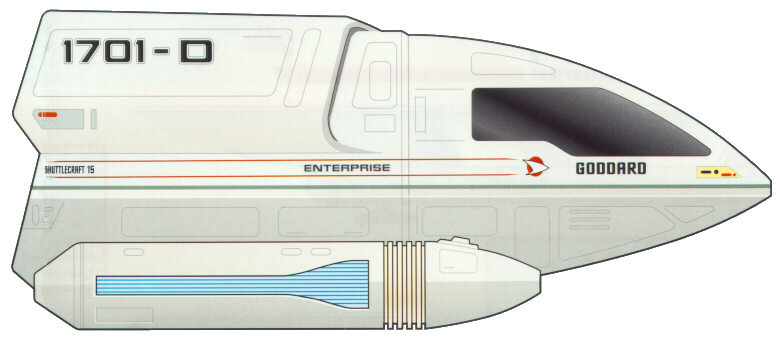
Type:
Light short-range warp shuttle.
Accommodation: Two flight crew, six
passengers.
Power Plant: One 50 cochrane warp engine,
two 750 millicochrane impulse engines, four RCS thrusters.
Dimensions: Length, 6.0 m; beam, 4.4 m;
height 2.7 m.
Mass: 3.38 metric tones.
Performance: Sustained Warp 3.
Armament: Two Type-IV phaser emitters.
The Type-6 Personnel Shuttlecraft is currently in widespread use throughout Starfleet, and is only recently being replaced by the slightly newer Type-8 Shuttle of similar design. The Uprated version of this vessel is considered to be the ideal choice for short-range interplanetary travel, and its large size makes it suitable to transport personnel and cargo over these distances. A short-range transporter is installed onboard, allowing for easy beam out of cargo and crew to and from their destination. Atmospheric flight capabilities allow for this shuttle type to land on planetary surfaces. Ships of this type are currently in use aboard virtually every medium to large sized starship class, as well as aboard stations and Starbases.
The Type-6 is perhaps the most successful shuttle design to date, and its overall structure and components are the foundations upon which the Type-8, -9, and -10 spaceframes are based.
Major technological advancements in the 2370’s allowed for further upgrades to be made to the engine systems aboard shuttlecraft. These upgrades make this craft more capable of long-range spaceflight and, like its starship counterparst, no longer damages subspace.
10.2.5 TYPE-7 PERSONNEL SHUTTLECRAFT (UPRTD)
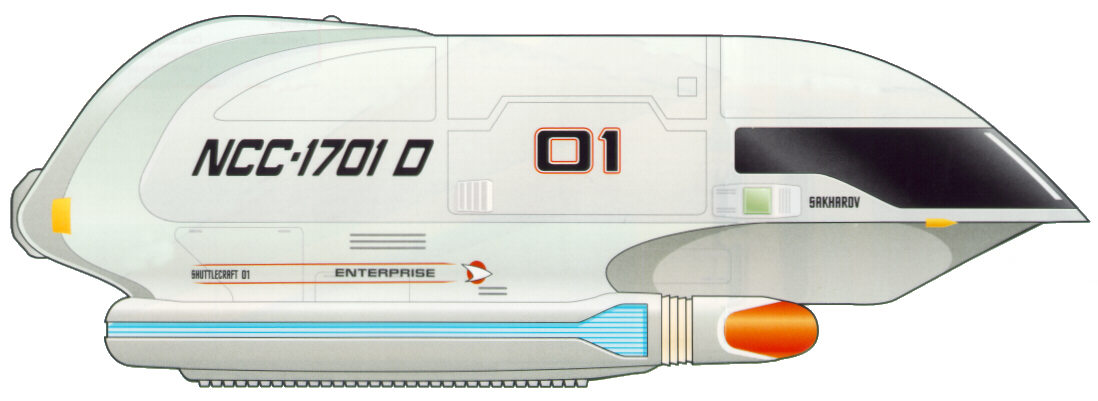
Type:
Medium short-range warp shuttle.
Accommodation: Two flight crew, six
passengers.
Power Plant: One 150 cochrane warp engine,
two 750 millicochrane impulse engines, four RCS thrusters.
Dimensions: Length, 8.5 m; beam, 3.6 m;
height 2.7 m.
Mass: 3.96 metric tones.
Performance: Sustained Warp 4.
Armament: Two Type-V phaser emitters.
With the borders of the Federation ever expanding as Starfleet reached the latter half of the 24th Century, the ASDB realized that there was sufficient need for a shuttlecraft capable of making the week-long journeys between planets and stations at low warp. The Type-7 was the first step in this direction, and is equipped for short-range warp travel. To offer comfort to its occupants, the shuttle contains a standard replicator system and sleeping compartments. The forward and aft compartments are separated by a small, informal living area that has a workstation and table. The aft area is normally equipped with a bunk area, but can easily be converted to allow for increased cargo capabilities. A medium-range transporter and atmospheric flight capabilities allow for the Type-7 to service starbases, starships and stations. Ships of this type are currently in use aboard most medium to large sized starship classes, as well as aboard stations and Starbases.
Major technological advancements in the 2370’s allowed for further upgrades to be made to the engine systems aboard shuttlecraft. These upgrades make this craft more capable of long-range spaceflight and, like its starship counterparts, no longer damages subspace.
10.2.6 TYPE-8 PERSONNEL SHUTTLECRAFT
Type:
Light long-range warp shuttle.
Accommodation: Two flight crew, six
passengers.
Power Plant: One 150 cochrane warp engine,
two 750 millicochrane impulse engines, four RCS thrusters.
Dimensions: Length, 6.2 m; beam, 4.5 m;
height 2.8 m.
Mass: 3.47 metric tones.
Performance: Warp 4.
Armament: Two Type-V phaser emitters.
Based upon the frame of the Type-6, the Type-8 Shuttlecraft is the most capable follow-up in the realm of personnel shuttles. Only slightly larger, the Type-8 is equipped with a medium-range transporter and has the ability to travel within a planet’s atmosphere. With a large cargo area that can also seat six passengers, the shuttle is a capable transport craft. Slowly replacing its elder parent craft, the Type-8 is now seeing rapid deployment on all medium to large starships, as well as to Starbases and stations throughout the Federation.
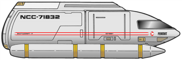
10.2.7 TYPE-9 PERSONNEL SHUTTLECRAFT
Type:
Medium long-range warp shuttle.
Accommodation: Two flight crew, two
passengers.
Power Plant: One 400 cochrane warp engine,
two 800 millicochrane impulse engines, four RCS thrusters.
Dimensions: Length, 8.5 m; beam, 4.61 m;
height 2.67 m.
Mass: 2.61 metric tones.
Performance: Warp 6.
Armament: Two Type-VI phaser emitters.
The Type-9 Personnel Shuttle is a long-range craft capable of traveling at high warp for extended periods of time due to new advances in variable geometry warp physics. Making its debut just before the launch of the Intrepid-class, this shuttle type is ideal for scouting and recon missions, but is well suited to perform many multi-mission tasks. Equipped with powerful Type-VI phaser emitters, the shuttle is designed to hold its own ground for a longer period of time. Comfortable seating for four and moderate cargo space is still achieved without sacrificing speed and maneuverability. As is standard by the 2360’s, the shuttle is equipped with a medium-range transporter and is capable of traveling through a planet’s atmosphere. With its ability to travel at high-warp speeds, the Type-9 has been equipped with a more pronounced deflector dish that houses a compact long-range sensor that further helps it in its role as a scout. The Type-9 is now being deployed throughout the fleet and is especially aiding deep-space exploratory ships with its impressive abilities.
10.2.8 TYPE-10 PERSONNEL SHUTTLECRAFT
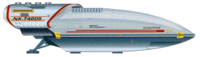
Type:
Heavy long-range warp shuttle.
Accommodation: Two flight crew, two
passengers.
Power Plant: One 250 cochrane warp engine,
two 800 millicochrane impulse engines, four RCS thrusters.
Dimensions: Length, 9.64 m; beam, 5.82 m;
height 3.35 m.
Mass: 19.73 metric tones.
Performance: Warp 5.
Armament: Three Type-V phaser emitters,
two micro-torpedo launchers, jamming devices.
Developed specifically for the Defiant-class starship project, the Type-10 Personnel Shuttle is the largest departure from the traditional role of an auxiliary craft that Starfleet has made in the past century. Short of a dedicated fighter craft, the Type-10 is one of the most powerful auxiliary ships, with only the bulkier Type-11 being more heavily equipped. Nonetheless, the shuttle sports increased hull armor and the addition of micro-torpedo launchers, as well as a suite of tactical jamming devices. A larger warp coil assembly, as well as torpedo stores, makes the Type-10 much more heavier then other shuttles. Elements from the Defiant-class project that were incorporated into the shuttle include armored bussard collectors, as well as a complex plasma venting system for use during possible warp core breech situations. This bulky craft is equipped with a powerful navigation deflector that allows it to travel at high-warp, and a complex sensor system makes this shuttle suitable for reconnaissance work. Able to hold its own in battle situations, the Type-10 is seeing limited deployment on Defiant-class starships, as well as border patrol vessels and combat-ready ships.
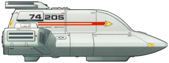
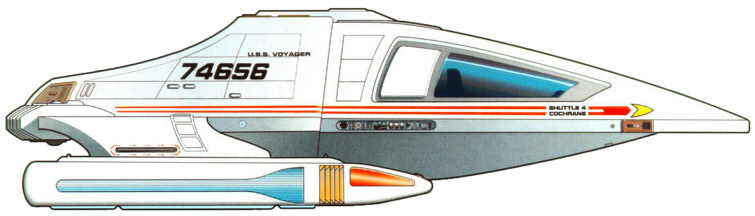
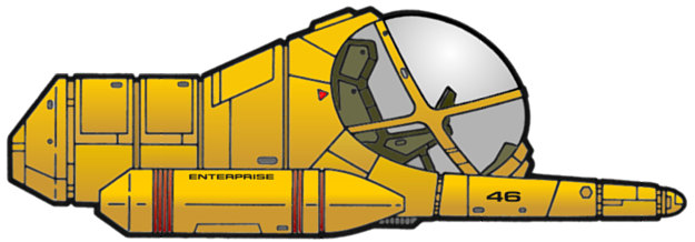
10.2.9 TYPE-10 PERSONNEL SHUTTLECRAFT
![]()
Type:
Heavy long-range warp shuttle.
Accommodation: Four flight crew, six
passengers.
Power Plant: One 400 cochrane warp engine,
two 800 millicochrane impulse engines, four RCS thrusters.
Dimensions: Length, 16 m; beam, 9.78 m;
height 4.25 m.
Mass: 28.11 metric tones.
Performance: Warp 6.
Armament: Four Type-V phaser emitters, two
micro-torpedo launchers (fore and aft), aft-mounted veritable purpose
emitter.
With an ultimate goal towards creating a useful all-purpose shuttlecraft, the designers of the Type-11 Personnel Shuttle set out to create a craft that was equipped with all the systems of a starship within the shell of a relatively small shuttle. Allocation of the larger Danube-class runabout to starships in the field proved too costly, and with the expressed need by the Sovereign-class development team for a capable shuttle, the Type-11 was born. Its overall frame and components are a meshing of lessons learned in both the Type-9 and Danube-class vessels. Impressive shielding, several phaser emitters, micro-torpedo launchers and a capable warp propulsion system makes this shuttle capable of performing a multitude of tasks. Both the ventral and dorsal areas of the shuttle feature a new magnaclamp docking port that is capable of linking up to other ships similarly equipped. A two-person transporter and a large aft compartment with a replicator adds to the shuttle’s versatility. The end hope is that these all-purpose shuttles will replace the more specific-purpose crafts already stationed on starships, reducing the amount of space needed for shuttle storage in already-cramped bays. The Type-11 is now seeing selective deployment outside the Sovereign-class to further assess its capabilities in the field.
Information on the Type-11 is relatively scarce, aside from a few paragraphs in Star Trek: The Magazine #1. Its classification is conjectural.
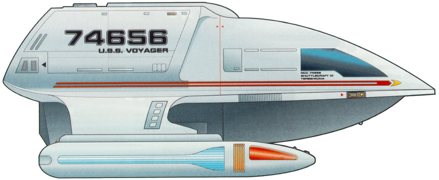
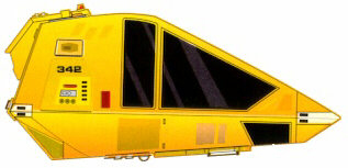
10.2.10 TYPE-9A CARGO SHUTTLECRAFT (UPRTD)
Type:
Heavy long-range warp shuttle.
Accommodation: Two flight crew.
Power Plant: One 150 cochrane warp engine,
two 750 millicochrane impulse engines, six RCS thrusters.
Dimensions: Length, 10.5 m; beam, 4.2 m;
height 3.6 m.
Mass: 8.9 metric tones.
Performance: Warp 4.
Armament: Two Type-V phaser emitters.
Short of a full-fledged transport ship, the Type-9A Cargo Shuttle is the primary shuttle of choice for cargo runs at major Starfleet facilities. Originally developed by the ASDB team stationed at Utopia Planitia, the 9A served as cargo vessel that carried components from the surface of Mars to the facilities in orbit. While able to travel at warp velocities, the 9A is somewhat slow at sub-light speeds, especially when carrying large amounts of cargo. The front of the shuttle is divided by a wall with a closable hatch, allowing for the aft area to be opened to the vacuum of space. The 9A also has the ability to carry one Sphinx Workpod in the aft area. A medium-range transporter and atmospheric flight capabilities allow it to easily complete its tasks. While rarely seen stationed aboard all but the largest starships, the Type-9A is a common site at any large Starfleet facility.
In response to the need to transporter ground troops into areas heavily shielded, a variant designated the Type-9B was designed and is capable of carrying 40 troops and their equipment to the surface of a planet or interior of a space station. This variant has seen limited service onboard frontline ships, most notably the Steamrunner-class starship.
Major technological advancements in the 2370’s allowed for further upgrades to be made to the engine systems aboard shuttlecraft. These upgrades make this craft more capable of long-range spaceflight and, like its starship counterparts, no longer damages subspace.
10.2.11 WORK BEE

Type:
Utility craft.
Accommodation: One operator.
Power Plant: One microfusion reactor, four
RCS thrusters.
Dimensions: Length, 4.11 m; beam, 1.92 m;
height 1.90 m.
Mass: 1.68 metric tones.
Performance: Maximum delta-v, 4,000 m/sec.
Armament: None
The Work Bee is a capable stand-alone craft used for inspection of spaceborne hardware, repairs, assembly, and other activates requiring remote manipulators. The fully pressurized craft has changed little in design during the past 150 years, although periodic updates to the internal systems are done routinely. Onboard fuel cells and microfusion generators can keep the craft operational for 76.4 hours, and the life-support systems can provide breathable air, drinking water and cooling for the pilot for as long as fifteen hours. If the pilot is wearing a pressure suit or SEWG, the craft allows for the operator to exit while conducting operations. Entrance and exit is provided by the forward window, which lifts vertically to allow the pilot to come and go.
A pair of robotic manipulator arms is folded beneath the main housing, and allows for work to be done through pilot-operated controls. In addition, the Work Bee is capable of handling a cargo attachment that makes it ideal for transferring cargo around large Starbase and spaceborne construction facilities. The cargo attachment features additional microfusion engines for supporting the increased mass.
10.2.12 TYPE-M1 SPHINX WORKPOD
Type:
Light industrial manipulator (Sphinx M1A), medium industrial
manipulator (Sphinx M2A), medium tug (Sphinx MT3D).
Accommodation: Pilot (M1A, M2A); pilot and
cargo specialist (MT3D).
Power Plant: One microfusion reactor, four
alfinium krellide power storage cells, four RCS thrusters.
Dimensions: Length, 6.2 m; beam, 2.6 m;
height 2.5 m.
Mass: 1.2 metric tones.
Performance: Maximum delta-v, 2,000 m/sec.
Armament: None
Along with the Work Bee, the various Sphinx Workpod types are a common site in any large Federation shipbuilding facility. Intended never to be far from its parent facility, the Workpod was designed to allow greater user hands-on control of the various functions involved with day-to-day construction and repair. With more tools then the Work Bee, the Sphinx M1A and M2A are used primarily to manipulate spaceborne hardware during construction. The Sphinx MT3D is a third variant of this robust design, and can be used for towing objects to and from the construction site. Furthermore, a group of MT3D units can work together to tow larger objects into place, including most starship classes, when large tractor emitters are not an option. All three variants utilize the same basic systems, and are small enough to fit inside of a Type-9A Cargo Shuttlecraft. All variants of the Sphinx Workpod are commonly found at Federation Fleet Yards and Starbases, as well as on larger Starfleet vessels.
A Buckingham Class Station is designated as a Support Station. Support Type Stations are usually mid-range facilities. Trying to define every mission that a Buckingham Class Station could perform would be a task that can't be completed. For the most part though, Starfleet uses Buckingham Class Stations to repair, refit, resupply, and refuel any allied vessel. Other tasks include linking the subspace network, providing local government, sector control, diplomatic, and other such duties. This justifies the expense in resources that it takes to build a Buckingham Class station.
The Buckingham Class has the standard mix of Operating modes. The first is Green mode. This describes the normal operating condition of a station. The second is yellow alert, this is a heightened state of alert where the shields are usually activated and the weapons brought to hot standby. The third stage is red alert; this is reserved for emergency conditions. Grey mode, also known as Reduced Power Mode, is where all non-essential systems on board are shut down to conserve power. This is usually used when more ships than normal are required to dock at the station. Separation Mode describes the set of operational procedures when the station is performing a module exchange. Detailed information on these and other operating procedures can be found in any Starfleet Database.
While briefly mentioned in 11.2 of this document, Separation Mode should be mentioned in more detail. The Buckingham Class is one of the first stations designed to be completely modular with the exception of its main structure. Prior to its creation this particular achievement had not been truly realized because of docking strengths. The necessary set up for this particular procedure is to evacuate all items from the module that is to be detached before it is disconnected from the station. After all inanimate objects are removed that can be, station personnel will slowly move out being sure to check each meter of the module to be sure that equipment is off. The hard connections are disconnected; this includes all the utility trunks. Finally the docking latches are disengaged [any welding is also sliced through with gamma torches]. The module is then towed away and the new module connected. The procedure essentially goes in reverse from here to make the new module usable.
Though much of a modern station’s systems are automated, they do require regular maintenance and upgrade. Maintenance is typically the purview of the Engineering, but personnel from certain divisions that are more familiar with them can also maintain specific systems.
Maintenance of onboard systems is almost constant, and varies in severity. Everything from fixing a stubborn replicator, to realigning the Dilithium matrix is handled by technicians and engineers on a regular basis. Main Engineering doesn’t check all systems centrally; to do so would occupy too much computer time by routing every single process to one location. To alleviate that, systems are compartmentalized by level and location for checking. Department heads are expected to run regular diagnostics of their own equipment and report anomalies to Engineering to be fixed.
Systems
Diagnostics
All key operating systems and subsystems aboard the station
have a number of preprogrammed diagnostic software and
procedures for use when actual or potential malfunctions are
experienced. These various diagnostic protocols are generally
classified into five different levels, each offering a different degree
of crew verification of automated tests. Which type of diagnostic is
used in a given situation will generally depend upon the criticality of
a situation, and upon the amount of time available for the test
procedures.
Level 1 Diagnostic - This refers to the most comprehensive type of system diagnostic, which is normally conducted on station's systems. Extensive automated diagnostic routines are performed, but a Level 1 diagnostic requires a team of crew members to physically verify operation of system mechanisms and to system readings, rather than depending on the automated programs, thereby guarding against possible malfunctions in self-testing hardware and software. Level 1 diagnostics on major systems can take several hours, and in many cases, the subject system must be taken off-line for all tests to be performed.
Level 2 Diagnostic - This refers to a comprehensive system diagnostic protocol, which, like a Level 1, involves extensive automated routines, but requires crew verification of fewer operational elements. This yields a somewhat less reliable system analysis, but is a procedure that can be conducted in less than half the time of the more complex tests.
Level 3 Diagnostic - This protocol is similar to Level 1 and 2 diagnostics but involves crew verification of only key mechanics and systems readings. Level 3 diagnostics are intended to be performed in ten minutes or less.
Level 4 Diagnostic - This automated procedure is intended for use whenever trouble is suspected with a given system. This protocol is similar to Level 5, but involves more sophisticated batteries of automated diagnostics. For most systems, Level 4 diagnostics can be performed in less than 30 seconds.
Level 5 Diagnostic - This automated procedure is intended for routine use to verify system performance. Level 5 diagnostics, which usually require less than 2.5 seconds, are typically performed on most systems on at least a daily basis, and are also performed during crisis situations when time and system resources are carefully managed.
12.1 EMERGENCY MEDICAL OPERATIONS
As on most ships and stations, the Buckingham Class has set procedures in case the station encounters a medical emergency which the various Sickbays cannot handle on their own. The Holodecks are pre-programmed with holographic medical facilities that can supplement those in Sickbay. At the same time equipment modules stored in the Cargo Bays can be set up there or one of the four Shuttlebays [development of antigrav platforms for Spacedock is still on going]. This equipment also provides extra medical facilities [with at least ten equipment modules dedicated as morgues]. When longer-term care is necessary, quarters onboard can be reconfigured to provide necessary medical support as well as private comfort.
Each pod can support a total of eighty-six person-days (meaning, one person can last eighty-six days, two can last for forty-three, etc.). Two pods are reserved for the top four officers in the chain of command on each station, because they are the last four to leave. As the number of experienced Captains dwindles in Starfleet, the notion of a Captain going down at his post has been abolished. If the station is abandoned, the top four officers in the chain of command will wait until everyone else is off the station, opt to arm the auto-Destruct (not always necessary, but there if needed), and then leave in the two escape pods. The current life pods are called ASRVs, or autonomous survival and recovery vehicles. The first group of these were delivered in 2337 to the last Renaissance Class starship, the USS Hokkaido.
12.3 RESCUE AND EVAC
OPERATIONS
![]()
In situations where more than one atmosphere is necessary it reduces the volume available for consistent density. An example of this is when one hundred persons of an N Class atmosphere must be evacuated along with ten thousand persons of an H Class atmosphere. As neither one can share the M Class atmosphere used aboard most Starfleet vessels, and they cannot share each other's atmosphere, each group must be separated from the others. This breaks down to the density of the H Class evacuees being much higher than that of the N Class or M Class, and thus also reduces the amount of space available for any other evacuee groups because the N Class is taking up space that it doesn't use but cannot transfer elsewhere.
The Transporter is an ideal way to evacuate personnel from dangerous locations. When transporting to the station the emergency transporters are not available, as these are beam out only. This is the reason for the difference between to and from station limits. However, in both cases the cargo transporters were utilized in the figures.
More detailed information on Rescue and Evac Operations, including those procedures involving the use of shuttlecraft can be found in any Starfleet Database.
When the station was originally designed, the Federation was very weary of adding a Self-Destruct system. The cost of producing a single station was so great that they preferred the risk. However, Starfleet brass was greatly infuriated with such a proposition. After weeks of all night sessions between a group of Federation Council members and Starfleet Admiralty a compromise was reached, and has become the standard for most Starfleet facilities.
When encountered with a situation requiring that the station be abandon, when eminent destruction of the station is in question, there are two options open to the Commanding Officer. The first is the option promoted by the Federation Council. This is termed the System-Destruct System. When activated by the Commanding Officer (in agreement with the Executive Officer) a countdown will commence (if one is specified). At zero seconds all primary & other critical systems on the station will be destroyed beyond repair, and if there are any sensitive systems (those which would be incredibly dangerous if they fell into the wrong hands) they are set up to be vaporized. The second option is the Station-Destruct System, which was pushed by Starfleet. This system is just like those used aboard Starfleet vessels, antimatter packages are placed in strategic areas on the station and explode to destroy the station. At the same time that the antimatter packages are released all the power generators on the station are set to overload [this is because antimatter packages were not placed around them to save space, time, and material].
Having two options did not satisfy Council members enough. They wanted policies to be set in place that would prevent a Commanding Officer from using the Station-Destruct System in all situations. In the simplest of terms the all encompassing policy that the Federation Council wanted was stated thusly; "If there is a chance, even the most remote possibility, that a station captured by enemy forces or a station abandon for any other reason, can be reoccupied by Starfleet within foreseeable circumstances without the enemy using said station to the great detriment of the Federation, then the System-Destruct System is the only option a Commanding Officer is permitted to employ."
APPENDIX
A - BASIC TECHNICAL SPECIFICATIONS ![]()
ACCOMMODATION
Officers and Crew: ~20,000
Visiting Personnel: 2,500-5,000
Civilian Population: Varies
Evacuation Limit: 100,000
DIMENSIONS
Overall Length: Depends on modules
Overall Draft 1142 meters
Overall Beam 1713 meters
ARMAMENT
28 Type-XI Phaser Turrets, 8 Type-IX Turrets, 16 Type-VIII Phaser Turrets, and module phasers
Six Torpedo Launchers capable of firing any Starfleet Torpedo ordnance
TRANSPORT EQUIPMENT
Shuttlecraft
Transporters
Spacedock: [There aren't numerical levels in this part of the station, but the listing here gives an idea of what is here. All are located in the central docking pier. Tiers describe more than one habitable level height, which are usually described in the "Tier A1" manner. This area, if it had a regular level layout, would contain more than 137 individual levels. Fortunately a good portion of this pier is taken up by moving docking gangways, and their mechanisms.]
Tiers A: Spacedock Engineering
Tiers B: Capital Ship Docking
Tier C: Spacedock Control, Spacedock Computer Core
Tiers D-F: Freighter Docking, Cargo Storage, Spacedock Doors
Tiers G-H: Passenger Ship Docking, Temporary Layover Areas
Tiers I-L: Cargo Bays, Shuttlebay 1, Ship Module Storage, Manufacturing Areas
Command Section: [45 Levels]
Level 1: Deuterium Storage Tanks
Level 2: Main Engineering
Level 3: Specialized Equipment Manufacturing Laboratories
Level 4: Life-support and Environmental Systems
Level 5: Starfleet Transporter Rooms 1-2
Level 6: Command Computer Core [next six decks down]
Level 7: Cargo Bays
Level 8: Operations, Captain’s Ready Room, Observation Lounge
Levels 9-12: Residential Apartments [Senior Officers only], Senior Staff Quarters
Level 13: Officer's Lounge, Medical Facilities
Level 14: Holodecks 1-2, Holosuites 1-8, Phaser Range
Level 15: Station Personnel Child Care Facilities
Level 16: Sickbay, Medical Laboratories, Gymnasium
Level 17: VIP Quarters, Starfleet Operations Briefing Room, Secondary Operations
Levels 18-24: Residential Apartments [Junior Officers only]
Level 25: Maintenance, Life-support and Environmental Systems
Level 26: Judicial Services and Brig
Levels 27-30: Cadet Barracks
Levels 31-32: Starfleet Training and Academy Services
Level 33: Subspace Communication Network Hub Control
Level 34: Cargo Bays
Levels 35-36: Science Labs, Station Government Offices
Level 37: Diplomatic Residencies and Offices
Level 38: Crew Mess, Medical Facilities
Level 39: Quarters [Non-Commissioned Personnel only]
Levels 40-42: Storage and Cargo Areas, Standard Cargo 1-2 Transporters
Levels 42-43: Quarters [Non-Commissioned Personnel only], Maintenance, Life-support and Environmental Systems
Levels 44-45: Permanent Civilian Residencies
Large Modules: [36 levels total, 18 levels per module]
For the most part the large
modules do not deviate from level to level in their arrangement. The
difference comes in how far away you are from the center of the module.
In the center of the module is a utility area. Out from that is a small
section for crew and junior officer quarters. Then a small cargo bay
area and shuttle landing pad. The next area is for commercial shops.
The section closest to the lateral hull of the modules is residential
areas, normally reserved for civilians.
Most stations will have one Large Module with a small docking bay on
top of it. This bay can handle civilian transport traffic with ease.
This is also a shuttlebay and cargo bay.
Small Modules: [18 levels per module.]
For the most part the small modules do not deviate from level to level in their arrangement. The difference comes in how far away you are from the center of the module. In the center of the module is a utility area. After that the rest of the module is filled with varying amounts of residential apartments.
This is the one point in this entire page where you'll find that, for the first time, I've stepped out of the Star Trek universe and back into our own 21st Century mindset. The information presented on this page is a result of hours and hours worth of researching, more researching and then a rigorous and intensive process of compiling the best information from canon sources, and making an attempt to fill in the blanks. For the purposes of ST:ACTD, these are the specs for the Buckingham-class station, like them or not. Now to address some of the problems found in compiling this information, followed by a brief explanation as to why a certain path was taken in these specs.
Approach: When designing these specs I took the approach that 1) the majority of things that were possible in the original specs had to be possible in these. 2) They needed to be consistent with evidence available. 3) They needed to be probable the way the stations are currently played. --- It would be impossible to use all the stations as base points, as I play on Arcadia Station, I choose it for simple ease. NOT out of a bias. Other team members used their experience on their ships to make the specs for those classes, not out of bias, but out of simple experience.
Design:
It took much discussion and debate within the group before we could
decide on which design to use. It was obvious that if we were going to
use the Mushroom design it would have to be significantly smaller than
the design we've seen on screen. This is based on a couple of reasons.
One is that the DS9 TM states DS9 is the fourth largest station under
Starfleet control, while this may or may not be true owing to the DS9
TM fallibility, we accepted it. At the same time, Mushroom stations are
extremely large; they take many decades to build even in Trek-time.
They are also very different than anything I have experienced in
playing on a station.
In an effort to do this we had to resort
to other designs. Every station ever shown on Star Trek was considered
[except for the drydocks and the K series from TOS]. The first ones to
go out of the running were Jupiter Station, Regula Station, and the
Orbital Office Complex. All three were either considered too small or
one time builds [unique to that one station]. We were left with the
stations from Utopia Planitia and the reused model of Regula as
Starbase 375. We eventually decided on the reuse of the Regula model.
This brought up an important side note...
Regula Station is not a Buckingham Class station. Nor is the Orbital
Office Complex. However the reuse of the model in TNG and DS9 are both
instances of the Buckingham Class station according to our current
specifications.
Size: Once we had decided on a design sizing should have been simple but it wasn't. Starbase 375 measured to be about 1 kilometer. The only difference was when Starbase 375 was shown with the captured Jem Hadar ship. This was only one scene, and the Jem Hadar ship has size inconsistencies already. It was decided to go ahead with the 1 kilometer height dimension. Then it was learned that this would make the bay smaller than we had intended it to be. Because the Regula model had already been used to represent almost any scale, we decided that no canon precedent would be broken if we make up with our own compromised size. Thus the size we came to was achieved.
Capacity: Our station cannot hold many of the larger ships. We understand this was part of the original promise, but unfortunately it couldn't be done. As our number crunching continues we will list those that can and cannot fit inside the bay:
|
Fit |
Don't Fit |
|
|
|
|
*The Excelsior Class fits barely; it will move extremely slow and must be maneuvered in one door then out the other [unless it reverses]. The Ambassador Class is too big on width, but only slightly larger on height. If it were only the height I would assume that the docking bay door was enlarged. The Nebula Class is the same as the Ambassador. The Akira is too wide, so much that I don't want to say that the station was modified like that. I'm giving the New Orleans Class the benefit of a doubt; it's only a few meters wider than the doorway; modification and inventive flying could do the trick. The Steamrunner Class fits in barely, but it has about a few meters to spare.
Level Layout: First some nautical nonsense, decks are used for ships not stations. After some word searching Level is used for deck on stations, and Tier became the description of the docking areas [which was originally called levels]. Next, you bet it's simple. I don't think anyone would want to make a detailed listing of over 150 levels. The docking bay should not have many habitable levels. It will have some, there is no reason to make visitors to the station stay at the other end where most of the civilian operations take place, and bringing the commerce to them is just good business.
Refits and Upgrades: With as old as these stations are, I'm sure Starfleet has upgraded them a few times. I included the EMH in this, but not Bio-Neural Gel Packs.
Starbase #: Stations in ST:ACTD don't have starbase numbers, and so I didn't make much mention of that. DS9 only had the DS number system; it didn't include the starbase system. Oh well.
Shuttlecraft: It is my personal opinion that it is quite silly to specify shuttlecraft. It is easy to replace them. As such I have only specified what kind of shuttlecraft the Buckingham Class has. This means however many personnel, cargo, shuttlepod, workpod, etc craft it has. I've also guesstimated how many runabouts there are.
Module Separation: I included this part because it only seems reasonable. Those look like detachable modules so why not make them such. There shouldn't be much difference in them at all except for size. I'm keeping their basic layout the same.
Breen Shield Defense: This is an accepted advance for all vessels, so why not the stations?
Weapons: I went with what seemed reasonable considering the amount of weaponry DS9 had, I probably should multiple my amount by ten... just kidding.
Phaser Complement: A debate arose over the Phasers for the station. After some time and a few other developments concerning the Excelsior Class the specs remained unchanged. The reasons for this are as follows: 1) Turrets aren't like Arrays; they have fewer Emitters covering the same arc. 2) Phaser type denotes power only. 3) DS9's phaser complement has many more arrays than this station does turrets.
APPENDIX
D - CREDITS AND COPYRIGHT INFORMATION ![]()
BUCKINGHAM-CLASS SPECIFICATIONS CREATED BY: JASON SHARP
SOURCES USED:
Copyright 2001 - Star Trek : A Call to Duty. Use of these specifications is restricted to the Star Trek: A Call to Duty (ST:ACTD) Technical Specifications domain at http://techspecs.acalltoduty.com and may only be reproduced with the express permission of the ST:ACTD on sites that clearly serve to provide information on ST:ACTD, its various ships and stations, or other related topics. Editing the contents of the information present on this page or reformatting the way in which it is presented is not permitted without the direct permission of ST:ACTD. Wherever possible, published sources were consulted to add to the wealth of knowledge in this document, and in some cases, this text was reproduced here. Sources used are properly cited in the "Credits and Copyright Information" appendix. No copyright infringement is intended.